• This topic has 4 replies, 3 voices, and was last updated 3 years ago by Avatar photoKen.
  • Creator
    Topic
  • #17162
    Avatar photoKen

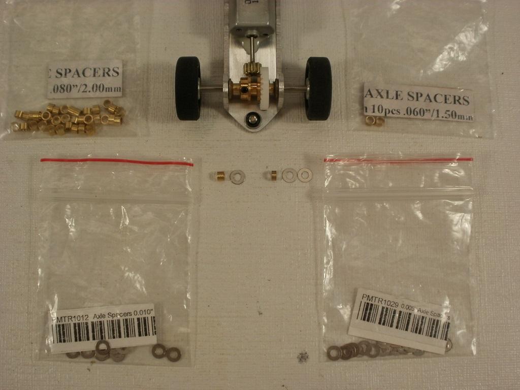
      This combination of spacers was recently used on the Beetle chassis. I measured the distance between the bushings. Then measured the crown thickness. I was very lucky in that the numbers were close enough without having to use too many spacers to take up the gap. The exact right number.

      They are sitting in order of how they sit on the axle.

      2mm brass and an 0.010″ inch steel spacer.    Crown gear.    1.5mm brass and 2 x 0.005″ inch steel spacers.

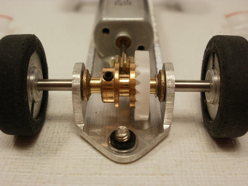
      Before gluing the motor in, the 0.010″ spacer was installed on the same side as the 2 x 0.005″ spacers. The motor was epoxied in place holding the gears tight to each other. After the 5-minute epoxy hardened. The axle was removed, and re-installed with the 0.010″ washer on the other side to create an exact gear mesh clearance.

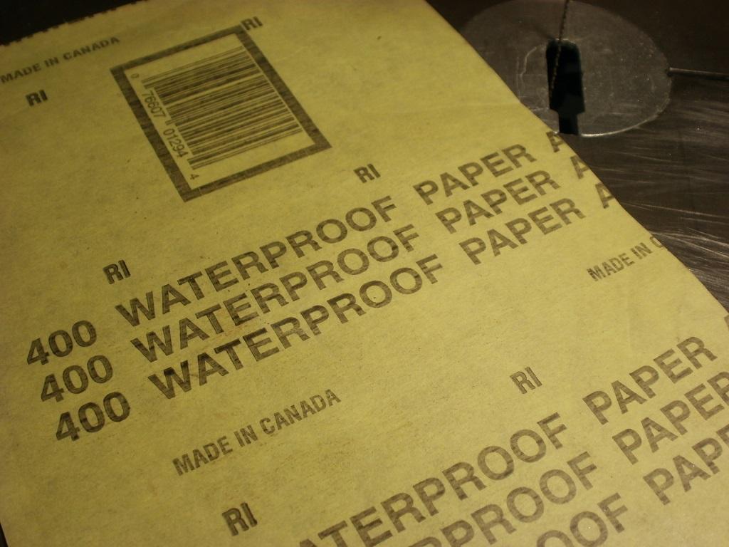
      The crown has raised letters that can interfere with measuring it. So I sand it smooth with 400-grit paper on a flat surface. I make small circles so as not to sand any side down more than the other.

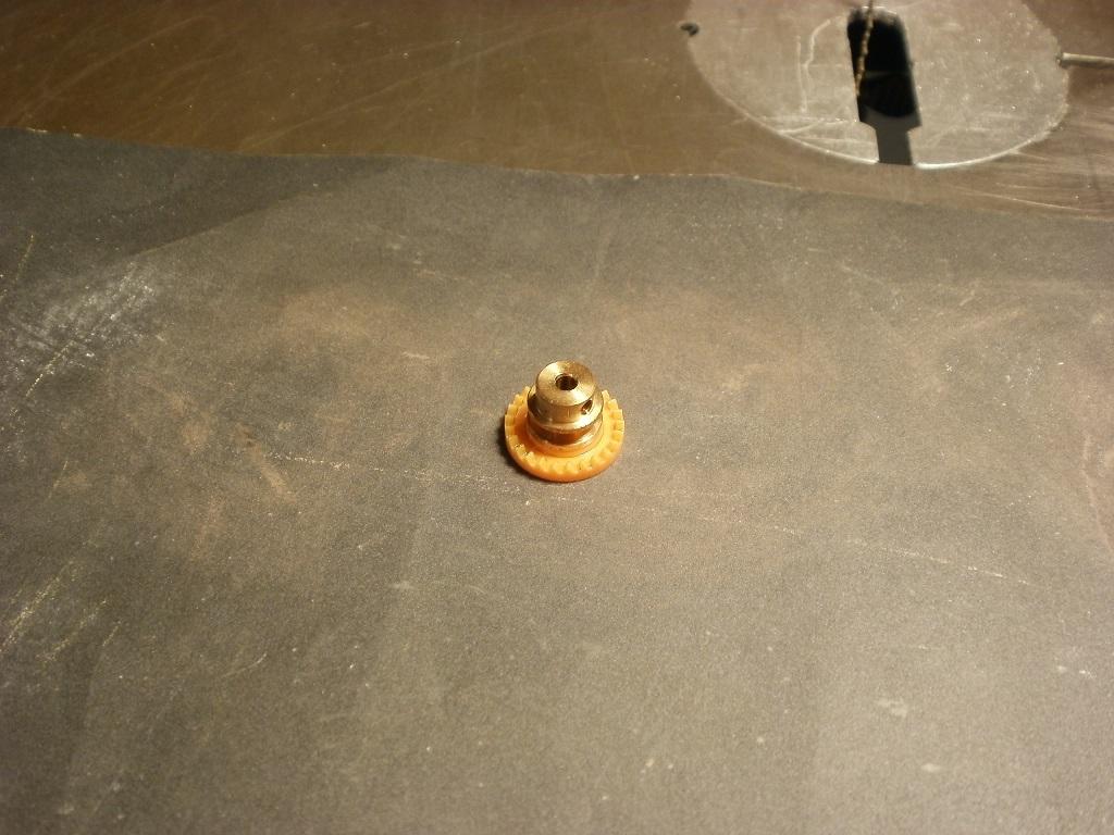
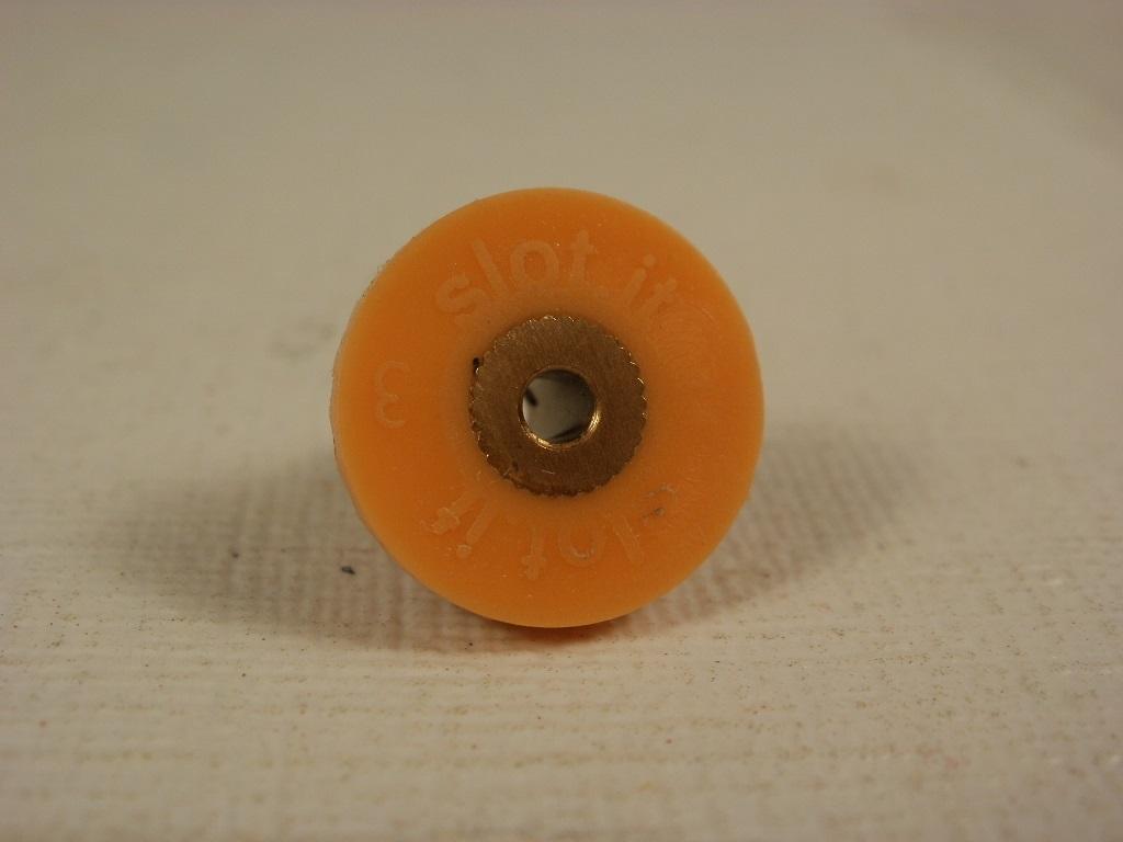
      What I found by mistake is that you can easily take a tenth of a millimeter off the width of the crown to help it fit better.

      Use the least amount of spacers as possible during assembly. They can have a bit of a spring-like reaction in larger numbers.

      Best regards,

      Ken

    Viewing 3 reply threads
    • Author
      Replies
      • #17163
        Avatar photoDB

          Ken, very good write up.

          One question, by switching the 0.010″ spacer what does that do?  Holds the crown tight against the pinion while the epoxy dries and then switching sides creates the free running mesh?????

          Thanks

        • #17164
          Avatar photoKen

            Thank you very kindly, Dave.

            Yes, you are 100% correct.

            The principal thought is to first set the crown with spacers on both sides so it rotates easily, but has almost no play side to side. The 0.010″ inch spacer must be on the opposite end of the crown/teeth.

            With the pinion attached to the motor, epoxy the motor in place with the pinion tight to the crown. Then after the epoxy hardens, re-install the spacer on the other side of the crown and you should end up with exactly 0.010″ inch space between the pinion and crown.

            Ken

          • #17184
            Anonymous

              Hi Ken, Your procedure assumes zero runout in either the Crown or the pinion, and while they are not horrible, the gears used by the plastic car manufacturers are far from perfect in this respect , therefore a purely mathematical measurement does not take this into account.

              If you glue your motor in the correct fore/aft position, and then add spacers to one side at a time while checking for lash at several positions on the Crown, you will eliminate any issues relating to runout.

              Cheers

              Chris Walker


            • #17185
              Avatar photoKen

                Thank you very kindly, Chris. Your advice is always appreciated.

                I once had Slot.It 27T black crown gear that locked up and could not rotate because it had a high spot within the gears. I thought that it was an odd thing to happen. I returned it and it was exhanged without issue. I have not seen it that far off alignement before or since. I assumed it was a fluke.

                Thank you kindly for the heads-up. I will spin the crowns on a drill and examine each one before use. :good:

            Viewing 3 reply threads
            • You must be logged in to reply to this topic.