• Creator
    Topic
  • #8202

    From the original Airfix Model Kit: 
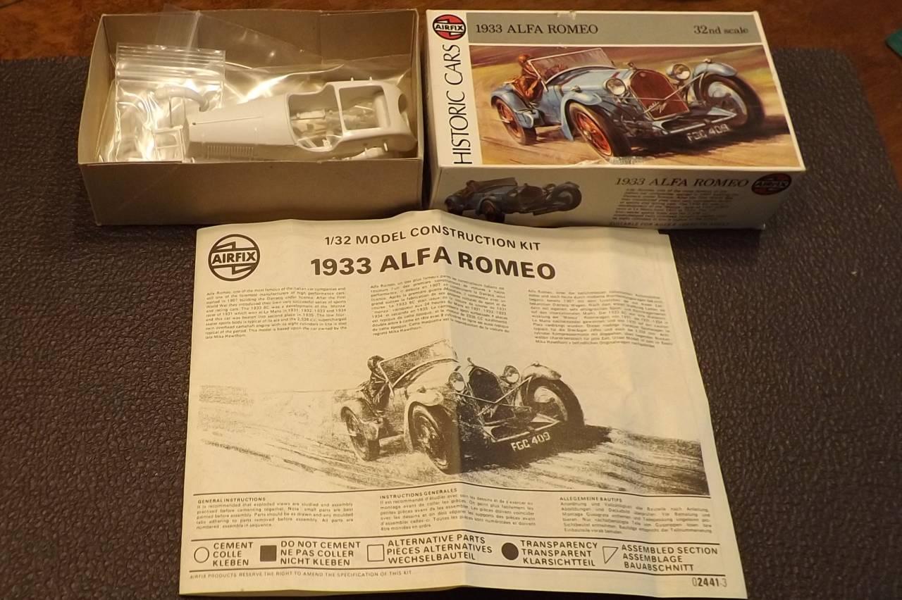
If you can’t read the fine print here it is:

    “Alfa-Romeo, one of the most famous of the Italian car companies and still one of the foremost manufacturers of high performance cars, started in 1907 building the Darracq under licence. After the First World War they introduced their own very successful series of sports and racing cars. The 1933 8C was a development of the ‘Monza’ racer of 1931 which won at Le Mans in 1931, 1932, 1933 and 1934 and this car was beaten into second place in 1935. The low four-seater sports body is typical of its era and the 2,336 c.c. supercharged twin overhead camshaft engine with its eight cylinders in line is also typical of the period. This model is based upon the car owned by the late Mike Hawthorn.”

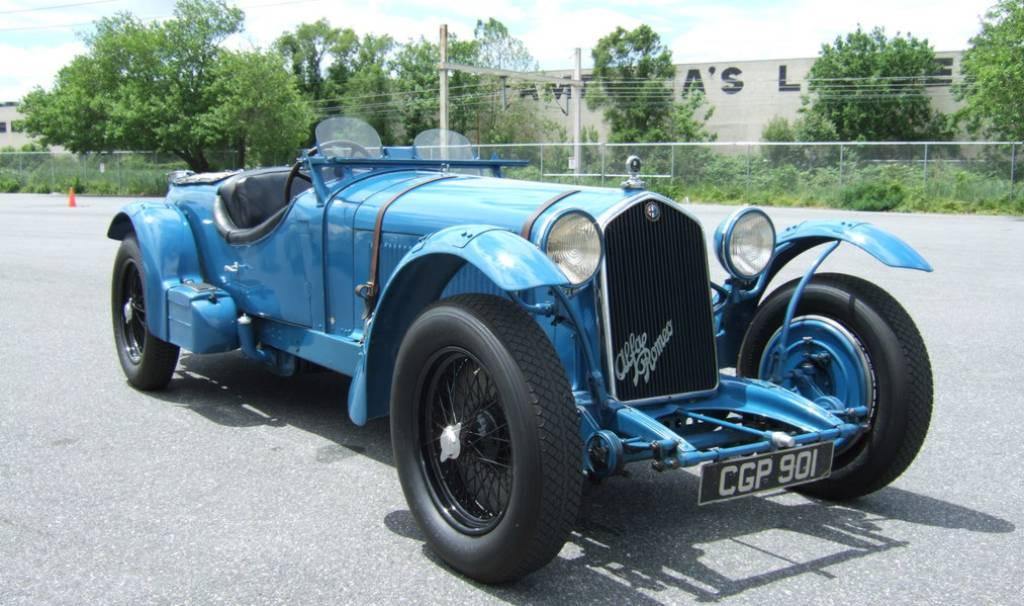
    So after doing a little research I decided that I would model a fantasy period livery in the same colour scheme as this 1:1 survivor (which is an 8c 2300 LM – with the round streamlined lid covering the spare tire(s)). A different version than the one I am building but I do like the extra single windscreens and since there were so many variants of this car that raced I will incorporate a pair of them on my model as well and leave the rest as is, including the uncovered spare tire. Racing number and pilot can be decided later… I do plan to paint the numbers in black.

    So after looking over everything I decided to start assembling (and welding) what I should in order to be able to sort out the dimensions for the chassis keeping in mind that everything must still be painted – so not everything can be assembled until after paint – and it is first mated to the chassis. I decided to leave the rear fenders separate since I wouldn’t be able to remove the body from the frame with them welded in place. So they along with the headlamps and other various bits will be painted separately and then epoxied together, as will the frame to the body.

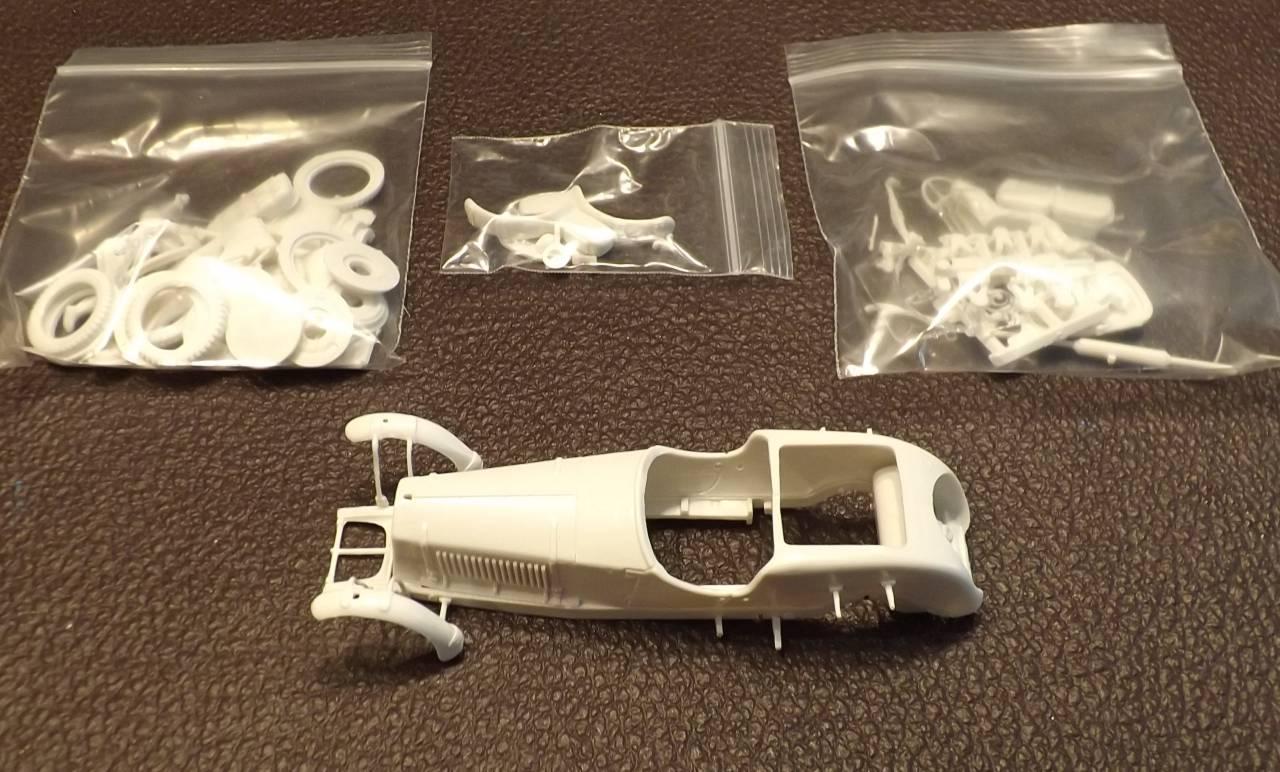
    I cut a channel into the floor to accommodate a mid inline ‘low power’ slim can motor and will decide later if it will be covered with styrene or a flexible piece of metallic plastic sheet. A front motor build would be nice but they are too much work and I would still need to cut away a portion of the interior – so why bother.

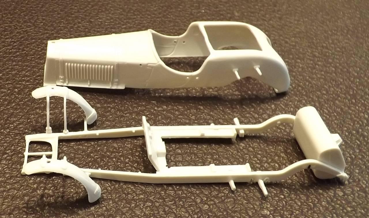
    Stock frame/suspension pieces such as leaf springs will be added to the frame or chassis after the chassis is built. Front axle/assembly will be determined on the fly as I build the chassis – I may use independent pins for each front wheel but we’ll see.

    In any event I plan to use and incorporate the following parts into this build:

    • BWMS050 motor w/10t true pitch pinion & 23t slot.it crown;
    • Slot.It round ‘self centering’ bushings with PM axles & spacers/washers (I like the very small size of these bushings);
    • Scalextric ‘stock’ round guide with quick change plate & Slot.It braid;
    • DArt wheels, tires & inserts plus DArt windscreens & pilot; and
    • Various K&B brass stock & wire.

    I was thinking about adding LED head and tail lights but that might be too ambitious right now – hopefully there is plenty of time in the future…

    Next Step: Building the Chassis (stay tuned…)

    The Happy Canadian Scale Modeler!

Viewing 18 reply threads
  • Author
    Replies
    • #8206


      Looks good Art. This is the kit that I have, but in the MPC labelled re-box; the rest looks to be the same (my post, June 25). When I got frustrated with planning the Ulster build, I was going to set it aside and go ahead with the Alfa first. I had thought it may have been easier since the body doesn’t wrap around to a pan chassis. (I finally have all the details of the Ulster planned out.) What you’ve done so far on the Alfa looks like a nice start. Lots of variants with the original cars, so we can easily go with different colour combinations even if we have a few of these; I may want to use some of your windscreen parts. I still haven’t found the function of those boxes projecting forward from the rear fenders; most of the photos I had seen showed small brass padlocks attached to them. It will be great to see all of these vintage cars running together on your track. I’m curious to see the rest of the build; Good luck with it.

      Felix.


    • #8209

      I’m anticipating a Coppa D’oro scheduled in September for our new PGP/PGP+ models so this build has been moved up the priority ladder.

      Regarding this model one more thing – I plan to locate the guide slightly behind the front wheel assembly to make sure it remains hidden… we’ll see – I should have it finished in a week or so… :good:

      The Happy Canadian Scale Modeler!

    • #8210
      Anonymous

        A very nice model.  Can’t wait to see the finished car running.

        In addition to the height of the chassis with tall wheels, guide placement seems to be a challenge with this vintage class due to the front wheels being situated right up front.  You typically want to have the guide in front of the front wheels but its not possible with the majority of these models.  The fact that its a slow motor class may balance this factor.  It will be interesting to see how they perform in comparison to other slow motor classes.  Regardless, I think they will look great running against each other at a slower pace.

      • #8211

        Just a bit of info that may be of some use. I’ve often wondered about what I would call the ‘golden triangle of slot racing‘. Is there a best proportion for the distance between the rear axle to the guide post, to the base width formed by the rear wheels? (called rear spur? – not rear track, since track is measured center to center on the tires) Is there a ratio of these two measurements that would give optimal speed and handling on straights as well as turns? I haven’t been able to get an expert opinion on this; I imagine it may be different for different cars and different tracks.

        The related question is the location of the guide post relative to the front axle, as has come up on these vintage cars. I have a relevant example. A pair of F1 cars came as part of a Carrera starter set I bought long ago. The wheelbase on these is 95 mm, the width between the outer edges of the rear tires is 60 mm, and the guide post is a full 15 mm behind the front axle. I recall that these cars handled very well at high speeds throughout the track, better than the GT cars. The wheelbase on the Alfa model is 98 mm long, and the rear base width is 48.5 mm. So this should be a good test to see how a similar guide position handles on these vintage cars.

      • #8236
        Avatar photoMiA

          Lovely!! Will make a spectacular addition to the vintage group. :yahoo:

          An 8C 2300 in period with the split screens. Slightly larger in appearance than the Broolklands screens that many marques used. Even came with a windshield wiper for the driver.

          If you discover/invent a source for the bubble headlight covers seen here,  the 1750 will need 3.

          A bit more research indicates that the 1750 I’m doing did in fact race with the full 1 pc. windscreen.

          Note the bottom of the running boards appear slightly above the axle centreline.

          You can certainly see the lineage between the 1750 and the 2300.

        • #8237
          Avatar photoKen

            Art,

            Nice looking model. The kit looks very detailed. Looking forward to seeing it completed.

            Would a 1930 Chevy pickup with a load of rum or beer be legal for that class? Just asking.  🙂

            Everyone’s going to need refreshments after the race.

            Ken

          • #8958

            Measuring twice so that I cut once… [visit our academy workshop chassis build session to download your copy of this printout] Motor has approximately 6mm clearance and the body exhaust detail is just a ‘c’ hair over 5mm clearance – making it a true PGP eligible model.  Driver figure in white [Chiron] took legs, torso, head & arms from four separate driver figures to fit properly into the seat with heat treated arms/hands to hold the steering wheel properly – 3 hours of fiddly unsatisfactory effort – until the final result. I typically glue the steering wheel into the hands of driver – as done here. Without white number decals that I was happy with I decided to paint all four by hand – most things never improve by reading about them – you need to practice for real. Extra tire and flat aero piece added to this model for a ‘LeMans’ look. Painted gauges, hemp wrapped steering wheel and other detailed interior pieces added. Clear epoxy used to glue everything. Body details painted by hand – all using Tamiya acrylics. Windscreen detail that came with the kit was chopped into two pieces so that it could be folded down and the frame painted a body colour – the upper folded portion dipped in ‘Future’ – and clear epoxy holds everything in place, including two piano wire rods which clean up the joint. Front grill number hand painted with acrylic, then washed with Citadel, then Molotow chrome added by hand… don’t try to do too much. Headlamp covers made from inventory headlight bezels painted in a metallic blue acrylic – I was contemplating molding a set of clear blue tinted bezel covers but opted not to.


            The Happy Canadian Scale Modeler!

          • #8959
            Avatar photoKen

              Absolutely stunning.  Amazing attention to detail!

              Ken

            • #8960

              The chassis consists of a standard rear end but using Slot.It small bushings so that they can be placed anywhere – why make this build more challenging than the others – performance? No need…

              To keep the front end of the plastic model true a straight axle couldn’t be used – so stubs were fabricated which would rotate within brass tubes soldered to a bent .055 piano wire… Independent front pins but fragile… note the model’s weathered suspension detail… Nothing unusual in this chassis build. Vintage guide held in place with a brass tube soldered into place and reinforced by a few triangles of wire… note the insulated stop wire to prevent over-rotation of the guide… Motor lead wire soldered to brass washers which were placed underneath the brass screws – and positioned through holes into the braid… Front pin spacers aren’t painted – I’m not a fan of painting them since contact with oil gums up the paint – a chemical solution is best – but still searching… Guide is old-school… Very basic rear end…


              The Happy Canadian Scale Modeler!

            • #8961

              I try to avoid complexity when it comes to mounting bodies. For this one I decided to float the body on the chassis using cut out styrene that would snap into place.

              Here is the rear end…Nothing fancy, but still allows plenty of body float… Getting back to the suspension detail provided… old school… …and back to the front end…

              The Happy Canadian Scale Modeler!

            • #8962

              This build – both chassis and body – are not for the newbie – make sure to ask if you need help… but first and foremost make sure you enjoy the build… BTW, this complete model weighs in at 64.7g…

              The Happy Canadian Scale Modeler!

            • #8963

              As always – feel free to share this thread with anyone who enjoys our hobby!!! :yahoo:  

              The Happy Canadian Scale Modeler!

            • #8964
              Avatar photoMiA

                WOW!! :wacko:

                Somewhere Vittorio Jano and his team are smiling!! :rose:

              • #8965

                Art

                A bijou masterpiece. The amount of detail you have been able to incorporate into a running slot car is stunning. I really appreciate the photographic documentation for this build. Would you please  give us a little more detail on how you developed your snap in mounting system as it looks like an elegant solution for narrow cars on wire chassis and some more detail (maybe even a mini tutorial?) on how you set up the front end with those those stub axles as it looks like the perfect solution for a period car.  Your work has inspired me to attempt the  1938 Maserati 8CTF that won the Indy 500 in 1939 and 1940 and I hope to integrate some of your techniques into it so that I can join you guys at a future Coppa D’oro.

                Cheers

                Steve

              • #8966
                Anonymous

                  BRAVO Maestro!  In Borats words…”very very nice”

                  Impressive detail.  Patients truly is a virtue.

                • #8967

                  Magfreakinifico!! :yahoo:

                • #8975

                  Thank you for the kind words!

                  The stub axles were cut from a leftover axle that was bent and instead of using a dubro #2 washer which would be too large in diameter I soldered a slice of brass tube (I believe it is the 1/8″ brass tube – the same stock that I used to sleeve the pin) to the end of each one and then filed each one smooth to make them run as well as I could. Using the jig & wheel blocks I soldered a bent .055″ wire to both the chassis and the brass sleeves to secure the front wheels/pins.

                  For low power cars I tried using sliced styrene tubing to mount bodies before and had good results – Using a slightly oversized tube you get perfect body movement – but you need to plan your basic chassis to accommodate the position of the tubing. Sometimes it just isn’t possible to do. In this case it was clear that three points would work just fine with the body/interior as it was – two along the rails and then one large one at the rear. Rear sideways play was controlled using shims or by removing material from either the body frame or the tube itself. If you use some plastic weld or crazy glue followed with clear epoxy the tubes become one with the body. The snap fit doesn’t need to be that tight – just enough to keep the body on the chassis when it is picked up or handled. The tricky part is fitting the pieces – but if your chassis is complete and you snap on your tubing to the rails and rear end of the chassis and then position it where you need it to be under the body so that everything lines up it is much easier. You may need to add shims underneath the tubes to make sure that the height of the model is correct and clearances are maintained. It is imperative that there be no rub with any moving parts whatsoever and to ensure this the chassis and unpainted body must be thoroughly tested on track. After paint if anyone needs to resort to a file or worse yet the dremel then shortcuts are usually to blame.

                  A future workshop might be a good forum for body mounting techniques. Perhaps something after the snow falls.

                  Cheers!!!

                  The Happy Canadian Scale Modeler!

                • #8980
                  Avatar photoDB

                    Stunning!  Can’t wait to see it in person.

                  • #20757

                    For more pictures of this model visit our scratch32 model gallery or CLICK HERE.

                    The Happy Canadian Scale Modeler!

                Viewing 18 reply threads
                • You must be logged in to reply to this topic.