
Forum Replies Created
-
AuthorReplies
-
Hi Gents:
I’ve registered for this race, since it’s the replacement for the event that I had registered for, just prior to the shut down.
If I’m allowed to attend, I will bring along my ‘Non Salivary-Exchange’ tire cleaner (my April 5, 2020 post, #14331), for anyone who wishes to use it. (It would be best if you clean off your rear tires on each of your cars with soap and water, or another disinfectant, before bringing them to the race, otherwise all follow-up precautions will be pointless.) As per Art’s April 6, 2020 reply, “moving forward we should eliminate saliva as a method of tire cleaning”.
The reason I say “if I’m allowed to attend” is that the originally scheduled event, I believe, had GT or CanAm as one of the classes, and I had a car in each class. It looks like the GT or CanAm may have been replaced with Trans Am, and I may not have a ready Trans Am car. I do have all the others.
Sorry Ken but I have to correct you. I was the one that came in last! Some nice racing on the part of other drivers.
A big thank you to JohnnySlots for offering those excellent replacement cars when a couple of mine died out.
Hi guys. Just had a chance last night to see the excellent race report by MiA, sorry for my late note. It looks like a great set of races on a beautiful track.
I was looking forward to being there. I’ve been collecting appropriate cars and this was the first event for which I had a car to run in each class; unlikely to have that matchup happen again for quite a while. After doing a lot of adjustments, upgrades and extra detailing, my cars were finally ready and packed up the night before, my ‘track snacks’ were all packed, and the driving weather was dry and sunny from my end.
Then I had a couple of side effects, nausea and dizziness, snuck in from all the medications I have been taking. I was hoping they would dissipate, but I finally had to give up. My apologies to the fellows who made it to the event, hope I didn’t cause any inconvenience.
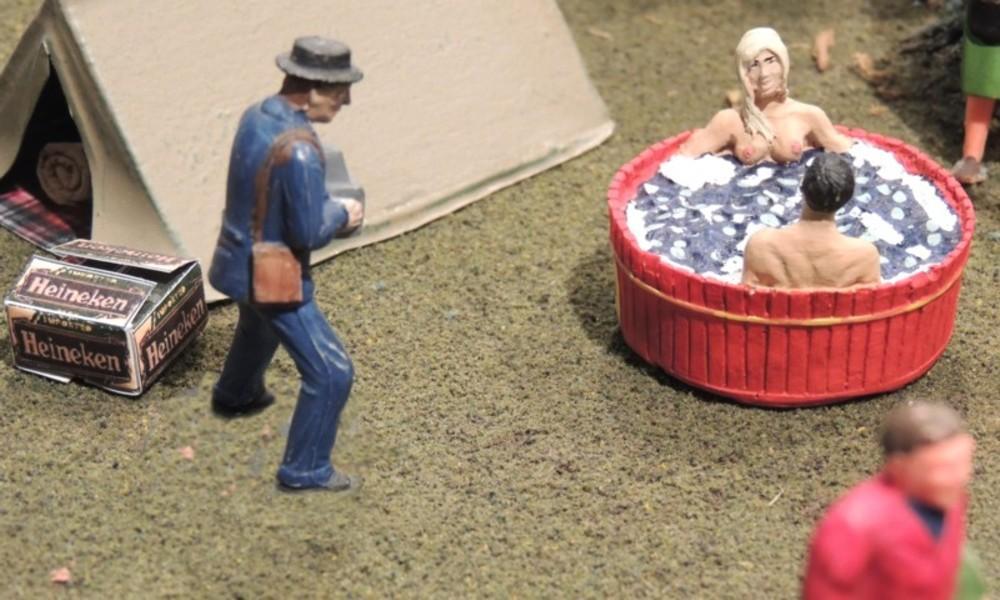
Thank you Porsche911 for hosting a great event. The stars finally aligned to give me a chance to see your excellent track. Beautifully scenerized as well; the cars on the hills off track were as interesting as the ones on. But I still want the phone number of that girl in the hot tub!
Felix
Great work Art, excellent design and build. A great running track, and true work D’Art !
Thanks for arranging the inaugural race. Felix.
Great work Art, excellent design and build. A great running track, and true work D’Art !
Thanks for arranging the inaugural race. Felix.
Thanks for your note, Ken.
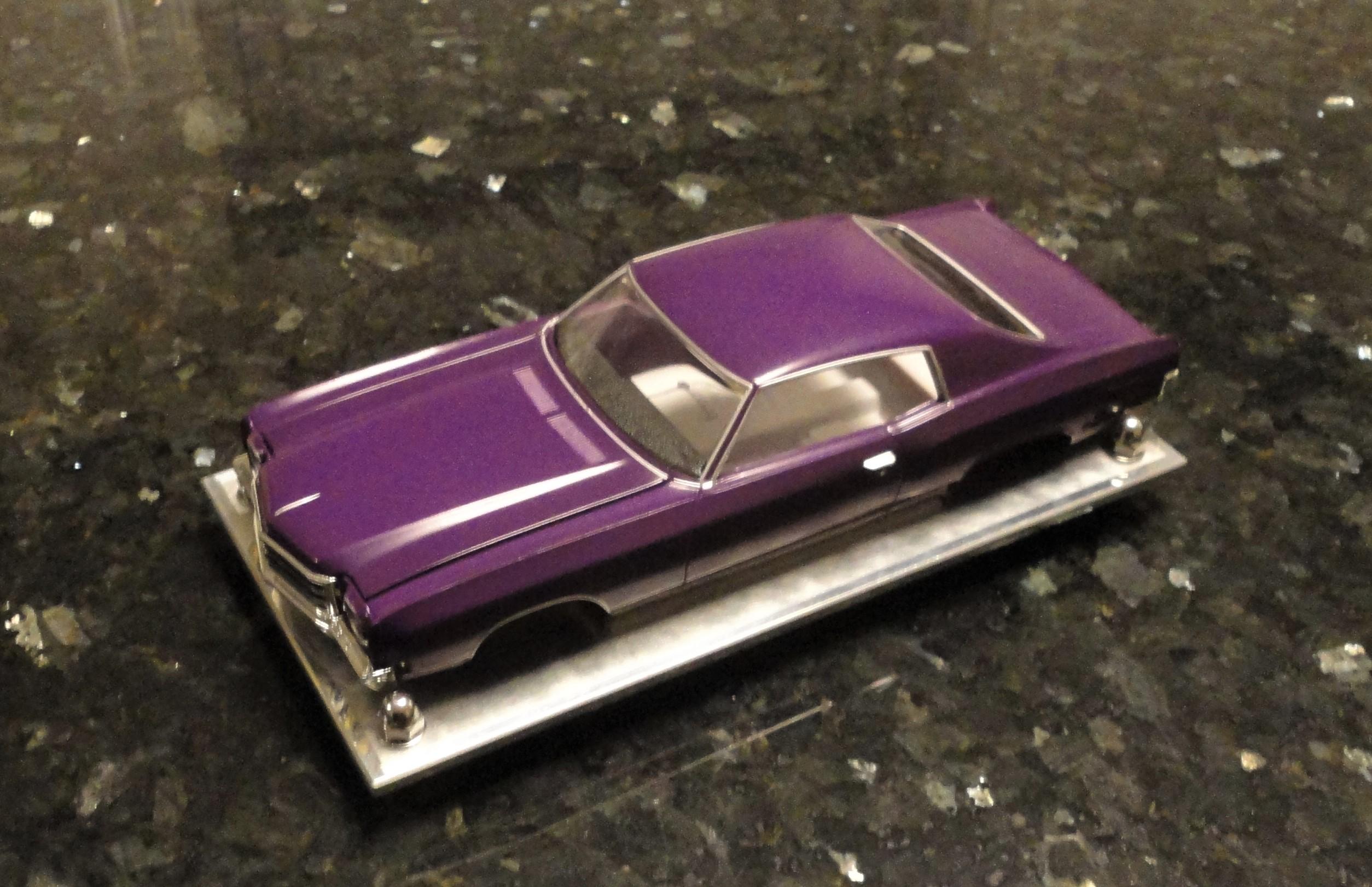
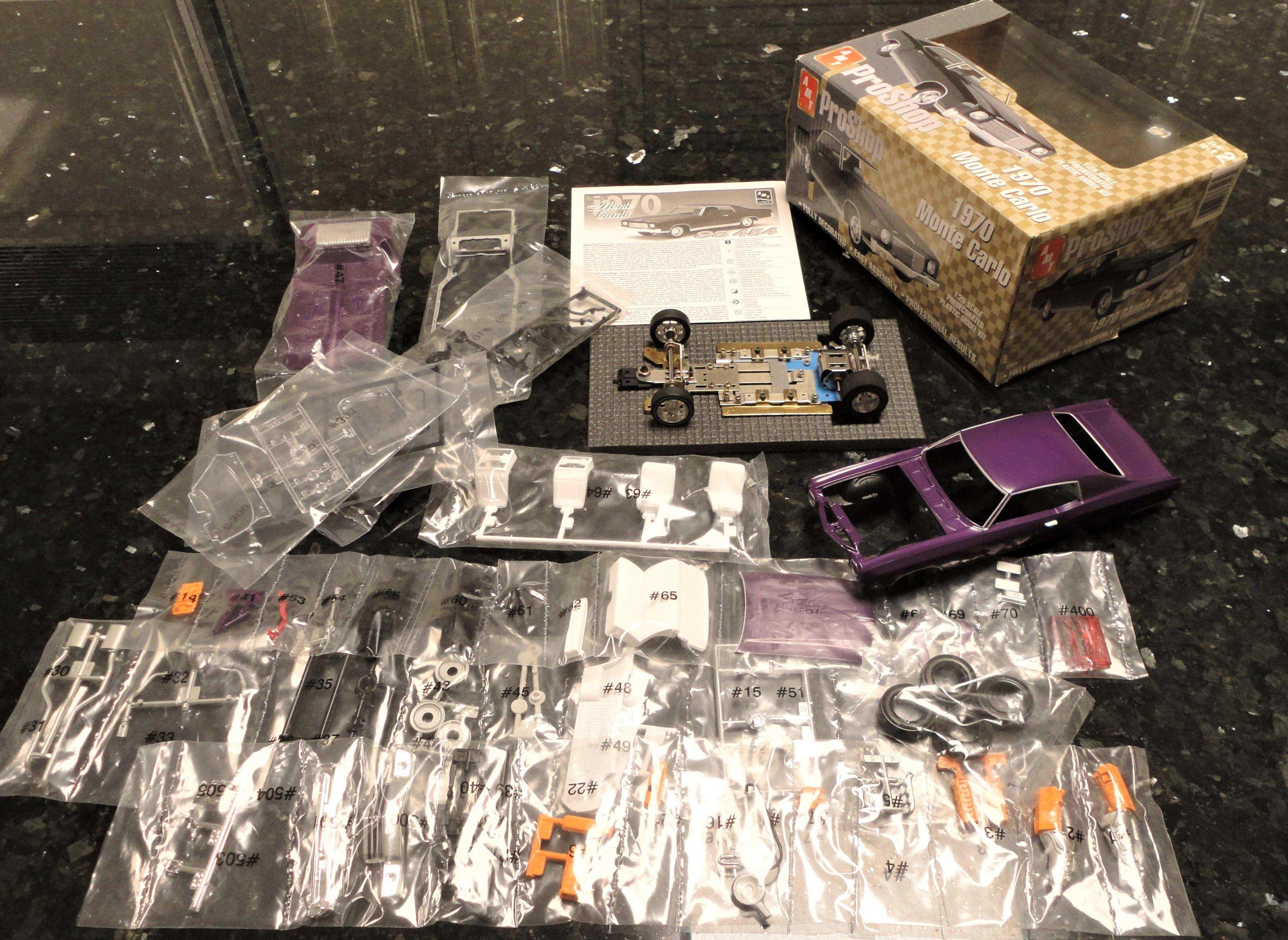
My Monte Carlo body in the photo is just at the test-fit stage (parts just taped in place); needs fit adjustments. Some of the others in the posts look very nice. Your chassis looks good, and the Fox10 is an appropriate motor for this use. That’s what I’ll be installing. I managed to find some raw material brass to make the extra parts I need for the chassis.
I don’t have an H&R. The one in my photo, above, is a PF 1300, a very early generation Pla-fit, a Japanese company with interesting and very significant contributions to 24’th scale racing. (See 4’th paragraph above, for curiosity.) I wouldn’t waste your money on an H&R chassis; it looks like a 50’s/60’s design in stamped light gage brass. There are a lot of compatibility problems with it. Also, you probably know how highly I regard inline gearing! One of our clubs tried to run a series with these chassis; it wasn’t very successful.
Hi Ken, thanks for your note; I hope you are doing well.
Nice to see you at the Grp25 show last month; every time I came by you had a bunch of people at your table so I didn’t want to interrupt. I had decided to drop by just as a temporary escape from all my eldercare duties, problems, and worries. I saw a couple of things worth buying, but I just couldn’t get into the buying mood.
I posted the Monte Carlo kit photo as a curiosity; didn’t know if the ones you got are from the same series. I got the kit long ago when we were planning to add another race series at the club I was in. But the series never materialized, then the owner moved and the track was sold. The kit is very unusual for AMT, with everything pre-finished and the painted sprues sealed in the blisterbags. The body is fully painted, but will probably need clearcoat. It’s 1/25’th scale, so, just 4% smaller than 1/24’th. This body has a WhlB = 120mm, FrW = 77mm, RrW = 76mm.
I’ve posted a few of my 24’th scale chassis here, but I’ve been hesitant in the past to post examples or discussion in case it was thought that I was trying to convince someone to go ‘to the dark side’ ! But since f1nutz, and now you, have done some of those postings I feel safe !
For those who have not used metal chassis in the larger scale, this one in my photo is a Pf1300, a very early generation ‘Pla-fit’ chassis, long out of production; not as sophisticated as the current versions, but a bit easier to adjust. Plafit chassis development has an interesting history and influence on 24’th scale racing. It’s a Japanese company that changed the nature of 24’th scale metal chassis with some very fundamental new properties (float, suspension, and linkage designs) that were quickly copied by some of the German manufacturers, like Schöler. The Plafits were adopted as the top competition chassis in the main northern European clubs. These guys are very serious about their toys and became the centre of the 24’th scale ‘slotcar universe’. The European pro-racers later started replacing the secondary parts of the Plafits with their own modified designs. They kept the large brass baseplate and the CNC’d bearing holders, but started modifying the aluminum H-plate and T-plate. They later started making these replacement parts from Carbon-Fibre plate, and Phenolic plate.
( The one in my photo is an old chassis, but the H&R one is archaic! After the wheelbase adjustment is bolted tight, the geometry and whole structure on the H&R is static. Also, it’s based on 1/8” axles which introduces another layer of incompatibilities on the bearings, gears, and wheels. The H&R chassis are also inline! )
This trial run is an interesting idea as a test. We will likely run into compatibility problems with parts, something that I still find irritating in going from 24’th to 32’nd scale; things are just done differently between the two scales, including some things that just don’t make any sense. Also, people who have tried a chassis that performs well in 24’th and downsized to 32’nd scale (like the Pf3300, a 32’nd scale version of the Pf1700), have found that it just doesn’t have the same dynamics in the smaller size. In the end, it seems that a ‘well-designed’ scratch-built brass/piano-wire chassis works best.
The 25’th scale will be tight on the track, but should be do-able on 3 ½” lane spacing. (Still, these are fairly large bodies. If the test fails for these ones, don’t be discouraged, it won’t necessarily fail for others.) If people are interested in running 24’th scale on Art’s tracks, there are a few other options, like 50’s and 60’s sports car model kits that are naturally smaller and would run well. I have a few other options as well, if people want to pursue the idea. There is also a whole new series of 24’th scale metal chassis finished slotcars out, that are being promoted as able to race on Scalextric track! I’ll bring one of them along to the next meet I attend.
Here’s a closer photo of the Monte Carlo body, in between some parts-fit testing and adjustment.
I don’t have a stash problem; I could stop buying any time I want to !
Felix.
? ?
Felix.
I built a Monte Carlo for this 1/25’th scale group, that I’ve illustrated in another reply post.
During our test session, I was surprised how well it ran on the track, especially considering that my chassis was assembled from left over bits and pieces; chassis components never designed for such a long body. So I thought, if I’ve gone to the trouble of building one, I might as well add another body as an alternate. At the Nova Ridge race last Saturday, Ken brought along the last two body kits, and I ended up buying both; the Starliner and the Bel Air. Good salesman!
Today Ken graciously invited me to pick up some parts from him for one of the body kits. I got an opportunity to see his excellent workshop, and some of his special techniques. I was able to see his professional machining equipment, and discuss some of the materials, methods and practices, with an expert ! (Things that I have to resort to doing by hand using various amateur tricks, when I’m making chassis parts.) He also showed me the progress on his ingenious down-draft paint booth.
An enlightening visit; thanks Ken!
Thanks Art, for organizing a nice race on a great track. It gave me a chance to finally try out a couple of new cars.
I did another record shutout of no wins ! ; something I plan to maintain – no motivation to do otherwise these days.
This is the most creative pair of model car bodies I’ve ever seen! The details are even more amazing close up than they are in the photos. The Colonel is a perfect likeness, and has wire-rimmed glasses fashioned from a staple – in 32’nd scale! The Rooster is a modified regular driver figure, with a beak-face added, and rooster crown (“comb”) on top and “wattle” hanging below the chin, and wing-hands, all made of flexible material. The car bodies and finishes themselves fit the theme perfectly. Excellent work, F1Nutz !
Very surprised and sorry to hear about this Ken. Being in an out of hospitals with various family members over the last few years, I have seen many positive results, beyond expectation. They have given me renewed confidence in medical science. Hospital staff have these procedures very finely tuned, so I’m hoping all will turn out well for you. Good luck with it; Best wishes.
Felix.
Best wishes Ken, for a full and quick recovery.
Felix.
February 26, 2022 at 10:20 pm in reply to: Lotus 30 – 351C with 2 x 4-barrel Holley carburators #24185Excellent Ken, car looks great; you did a superior job all around.
I’m glad the velocity stacks worked out for you; happy to have made my small contribution to the cause. FelixThank you, gentlemen. I am humbled by your words of encouragement. (I must say, it was never my intention to do so much work on this body shell.) Sorry that I can’t devote the time needed to move the project along at a more respectable pace.
Excellent work Louis. Looks like you are getting to be proficient at the scratch-built chassis; some of us will have to catch up. It’s good to see another sidewinder configuration, and it appears that it has allowed you to use a full interior. Beautifully authentic body finish as well.
Part E: Continuing work on the Sprite body; First step in correcting the headlight aim.
(Rather than random half hour intervals, this detailed work requires larger blocks of free time. For the reasons I’ve shared with members privately, I have had considerable difficulty finding that time to devote to the hobby. Sorry for the slow progress on this work.)
I’ve moved on to work on correcting the tooling errors related to the headlight pods on this model. For easier reference, I will list here, the main defects I had earlier described related to the headlight pods. ( For the full discussion, see post #18635, June 7, 2021, paragraphs – 2, 3, 5 ; four distinct errors in the tooling of the headlight domes on this Airfix model, referring to Fig’s 6 [from post #18598, May 21], and 7, 8 [from post #18635, June 7, 2021]. )
On the real car: the front face of the headlight sockets are round, to fit the round headlights, (rather than elongated as illustrated in Fig 6 of the Airfix model); The headlight pods on top of the bonnet have a very pronounced curved shape; The profile of the top surface of the pods ends horizontally as it reaches the front; The front face of the sockets is vertical so that the headlight aim is horizontal. (These last three features are illustrated clearly in previous Fig. 7 and 8; comparison between the real car and the Airfix model.)
At this step in the work, I am trying to correct the headlight aim back to the horizontal. There are two methods that can be attempted to achieve this. One is to cut into the face of the lens sockets of the headlight pods to make the leading edges vertical. However, as previously described, there is already a gap in the body shell between the top and bottom of the lens sockets when viewed directly from above, and this method would create an even larger hole at the bottom of each socket. The second method is to extend the lens sockets forward by adding small angled sections to make those leading edges vertical. This method will also have the advantage of allowing for the correction of the profile of the tops of the pods, that is, allowing for the formation of a curve on the top surface, re-shaping it to end horizontally when it reaches the front.
I started by carefully aligning the body shell to the grid and clamping it into place :
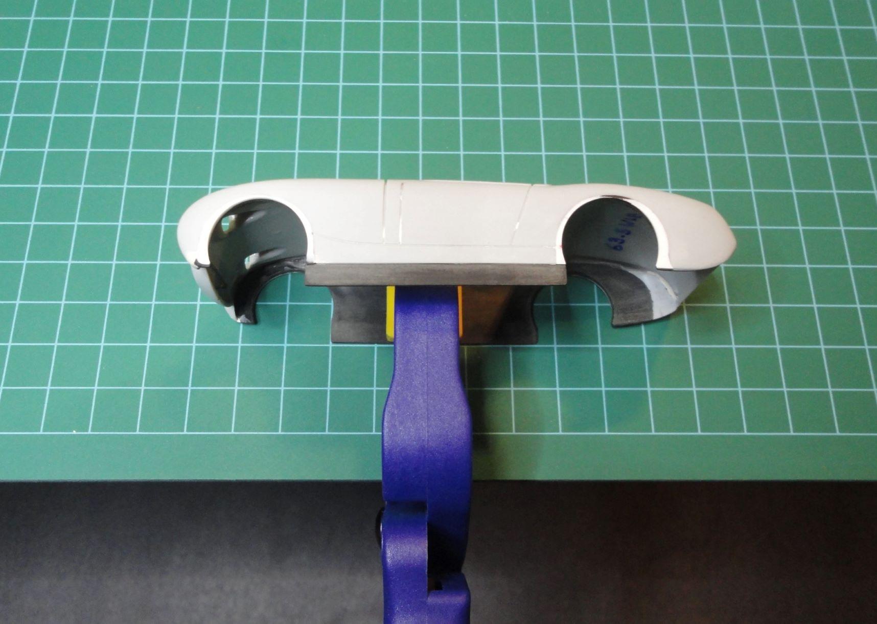
Fig. 17: Body shell accurately aligned to the grid and clamped in place.
I have ¼” diameter polystyrene tube which I cut off square in a mini mitre box. It fits well in the cupped form on the bonnet, pushed flush up against the face of the headlight socket. (I checked that the tube was straight – it rolled freely on polished granite slab.)
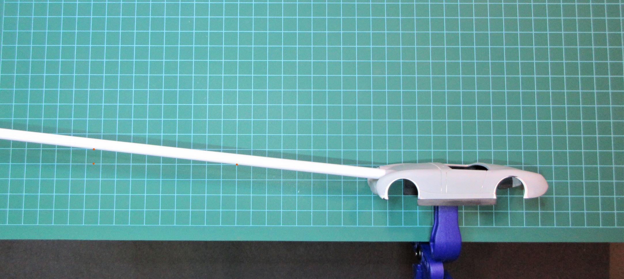
Fig. 18: Polystyrene tube pushed flush up against the face of the headlight socket shows the true angle of inclination of the headlight aim.
Here we have the first clear illustration of the headlight aim. The error in the aim is very obvious. It’s a significant deviation from the horizontal. ( Again, the headlights would do a good job of illuminating the tree-tops along the English countryside! ) In order to do an accurate correction, we need to measure this angle of elevation.
Some basic trigonometry and application of the inverse-tangent function on the rise of 1 grid unit over the run of 9.5 grid units (see red reference dots in photo), calculates the angle of inclination at 6.0090° .
Well, any proper measurement deserves another! As a backup, I decided to do a direct measurement using an extra large drafting protractor.
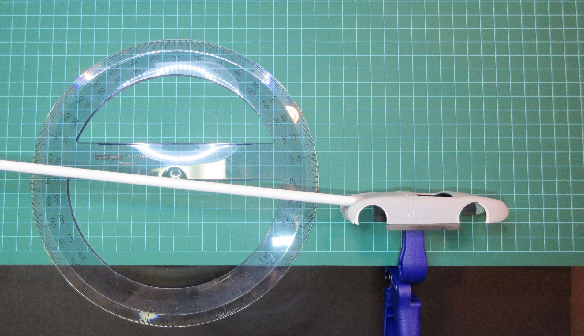
Fig. 19: Protractor measurement shows a 6.5° angle of inclination.
Direct measurement of the angle using an extra-large protractor gave a clear 6.5° angle of inclination of the headlight aim. (All of these measurements involve visual judgement: where the edge of the tube crosses the grid line, for the trigonometric calculation method; where the edge of the tube crosses the protractor line, for the direct measurement method. However, a careful protractor measurement requires viewing the intersection of the tube edge and protractor scale immediately above each separate intersection point, which can not be done with the single view of the camera. That careful measurement read a clear 6.5° for the angle of inclination of the headlight aim.)
What can we conclude from this exercise? Is the angle of inclination of the headlight aim on this kit 6.0° to 6.5° above the horizontal? Quite convincingly so, but possibly not convincing enough for all? What we can certainly conclude is that, in the tooling of this kit, the headlight aim is far too high above the horizontal and needs to be corrected. Also, our best estimated measure of the required correction is about 6.25 degrees.
This has turned out to be an exercise in perseverance ! Until next step; Different time, same channel ! Felix
Thanks Art, for your considerate words of encouragement. I got to the hobby shop and picked up some raw materials to work on the light-pod corrections, and on the chassis. I think I have a solution for the headlight adjustments, and by hook or by crook, I will make it work!
Part D: Work completed on correcting the wheel-well cut-outs: (I haven’t had much time to devote to the hobby recently but managed to get this stage of the work finished.)

Fig. 13: White adjustment plates re-marked for grinding out.
As expected, I found that there wasn’t room in the seams to hold any body putty; there are a couple of spots at the bottom corners of the adjustment plates. The surface colours are deceptive, grey-white-black-beige areas. The seams and surfaces are in fact, all completely smooth. Here I have re-marked the cut-out boundaries, ready for drilling and grinding out.

Fig. 14: New correct wheel cut-outs are drilled and ground.
Starting with a small drill bit at centre, moving up through various stone bits, I ground out the openings. This final stone was used to bring the wheel openings to 18 mm diameter.
I discovered long ago, that in order to enlarge a hole in most materials, it’s best to use a conical grinding stone. It allows uniform contact and cut along the whole circumference, increasing the size of the hole, while keeping it centred and keeping it circular. On the other hand, a cylindrical stone or a sanding drum only contacts at one point and relies on moving that one contact point uniformly around the inside of the circle.

Fig. 15: Some of the excess black backing plate is ground away.
Excess backing sheet at front and rear has been ground off, and bottom in between the wheels has been cut down a few millimeters. It will be sanded down further after final adjustments are done on the bottoms of the cut-outs during chassis fit tests.

Fig. 16: Right side view.
From Fig 16, it looks to me that the front right wheel opening is cut back too far; the space between the front edge of the cut-out and front edge of the car looks much larger than on the left side, shown by Fig 15. After all this work, that looks like a major grinding error on my part. Is it possible that the grinding tool migrated during the cut?
That frustrated me to some significant degree! So I set out to do some tricky measurements on those curved forms. I set the body on its side on the operating table, and held a long plate up against the bottom edge. I placed a block up against the plate and in contact with the leading edge of the body. That allowed me to use a caliper to accurately measure three perpendicular distances from: (a) the front edge of the body to the front edge of the wheel cut-out; (b) the front edge of the body to the wheel centre; and (c) the front edge of the body to the back edge of the wheel cut-out. As a more general back-up, I re-measured using a small steel ruler.
Value (a) measured at 6.0 mm. Value (b) measured at 15.0 mm. Value (c) measured at 24.5 mm.
When I went to the left side, the measured values came out the same, when rounded to one decimal precision, to my surprise and great relief. The key result is that the distance from the front edge of the body to the front edge of the wheel cut-out is now the same on both the left and right side of the body; 6.0 mm, to two significant digit accuracy and one decimal digit precision. These measurements also verify that the front wheel cut-outs are now correctly centred at the same distance from the front edge of the body.
(Recall also, that the wheel openings were ground out to an 18 mm diameter. The above measurements also agree with that, in that 6.0 to 15.0 is 9.0 mm, and 15.0 to 24.5 is 9.5 mm, each value representing the approximate radius of the cut-outs.)
I discovered early on with this model kit, that besides the elongation of the front cut-outs contrary to the shape on the real car, the original cut-outs on the model have slightly different shapes, sizes, and positions, between left and right sides. As indicated in the photos of my previous post as well as this one, the front-right wheel opening was different from the left, and needed the largest adjustment to shape and position.
Next stage of work is the correction of the headlight sockets; adjusting them to a round shape and adjusting the aim to the horizontal.
July 9, 2021 at 10:35 pm in reply to: July 5, 2021 (10am – 2pm) Rule Twerks & Open Track Practice #18880Hi Steve, Ken: Great discussion. I agree with all that’s been said, except for one correction that arises from chassis geometry. The FF050 is a slimline long-can motor that will not fit into a sidewinder configuration (and still allow room for gearing, bushings, chassis members, spacers, and wide wheels). Since we are allowing for any motor configuration, we need to allow for a short can motor with a comparable rating. I suggest we just put a limit on the max RPM, since torque is not an accurately measured value in these motors.
The ’41 Willy’s Coupe is a great example at 62.5mm wide; I didn’t know that body was available in 32’nd scale. It would be great to include it in our range of cars. The rear stance still seems to be the key factor of discussion, and we are still going back and forth a bit on it. So it’s probably the first thing we have to finalize. Since it’s an area of concern for other members, it may be best to specify both components of the width, the ‘track width’ and the absolute overall width to outer edge of fenders whenever present. That may inspire a bit more confidence and acceptance of the ruleset. (By the way, note that we are using rear ‘track width’ to mean ‘rear spur’, since track width is actually defined as centre-to-centre width between the wheels. Track width seems to be the more common usage on the hobby.) Since we’ve agreed to run the HR+ class separately if or when scheduled, that should give us a bit more leeway on the final widths. From this last exchange, it looks like we are tending toward 60mm ‘track’ and 63mm overall width, which seems fine to me, but open to further discussion.
A sit-down meeting over coffee is a good idea. I can get to most areas in Scarborough in about 45 min or less. If I make special arrangements with my assistant (boss!), I can get free for a few hours after 2pm on a couple of days a week. (Some evenings are also possible.) So lets try to work out a time and place. (Being forum moderators, I assume we have each-other’s email addresses? If so, send me a note.)
July 8, 2021 at 11:30 pm in reply to: July 5, 2021 (10am – 2pm) Rule Twerks & Open Track Practice #18873Ken, Steve: Let’s collaborate on the builds for this HR+ trail, so we cover a larger range. The overall width is the key factor in question, so we all need to test it, in some form or other. I would like to try a sidewinder configuration, full fenders- widened, large wide rear tires. (In terms of build time, I still can’t make any promises; even if I drop other projects, there’s other work I can’t get around. I will certainly reduce my obsessive requirements on quality and aesthetics, since this will be just a trial run.)
July 8, 2021 at 11:22 pm in reply to: July 5, 2021 (10am – 2pm) Rule Twerks & Open Track Practice #18872Ken, thank you for your note, and for your support for the HR+ proposal. I know you had some constraints impacting your build of the ’32-Ford, and that was the original seed of this whole discussion. Since you have had that experience with the restrictions, and since you are going to be the first to build the new class and I will be the last, I request that you build the biggest most modified bad-ass Hot Rod you can!! Set the limit and go past it!
Art, thank you for your thoughtful contributions, and for your accommodation in allowing this subclass a trial run. In the end, I think it will be a good thing for the club as a whole, and that’s been the objective. Of the suggested options under HR+5, the choice of scheduling the subclass to race separately is fine. Perhaps it won’t be scheduled very often, or it may take off and become popular; either is OK. Now, I know that you know that I know that you know that it is very unlikely that I will have a car built by the test run!! If I do, it will be the ugliest thing on the track, chassis and body!
July 7, 2021 at 11:40 pm in reply to: July 5, 2021 (10am – 2pm) Rule Twerks & Open Track Practice #18867I was surprised and disappointed at the process. I wasn’t going to respond further, figuring it was pointless, but with the obvious errors in fact and in reasoning, I concluded I must follow up. I have commented separately on each of the replies above. (Sorry, I couldn’t sugar-coat my responses.)
I have yet to find any valid reason for the strong resistance to making the small change to the ruleset that we are recommending as HR+. We made a very well reasoned initial submission that was rejected completely. We have responded to all follow-up concerns with practical solutions to each, completely addressing the stated concerns. It appears that none of these have been given due consideration.
We are using Slow Motors in order to avoid any competitive advantage in the HR+. (As you know, the SP+ class has ‘Open Unlimited’ motors, that do produce an advantage.) We have addressed the concern of potentially having an adverse affect on cars in the next lane, by proposing various compromises that completely resolve the problem: either reduce the HR+ max width to 60mm; or, not run the HR+ on the 3” lane spacing tracks; or, require HR+ to be closed wheel cars with full fenders, at 62.5mm max width, (the same width as the SP and SP+ classes).
I have a model of the ’34 Ford I bought from the Grp25 show that I have stripped and separated. Some of the parts need repair, but I was planning on doing it as a scratch-built Hot Rod. Not a fan of fender-less ones, I was planning widened the fenders, as on many of the real cars in the class. That’s part of my motivation in this discussion. The other part, believe it or not, is to improve the range and quality of models in our club; to improve the club, not to hinder anyone or to undermine anything. However, given the current state of affairs, I may be forced to build a version of the car that I am not interested in. Even then, judging from other builds, I may still end up with an unrealistically exposed chassis in order to conform to the 50.8mm max width.
For the record, this is a summary of our current recommendation for the HR+ subclass, accounting for the concerns raised and the accommodations we made to address those concerns and solve any related problems (four possible options given to address concerns on overall width):
HR+ 1. Any modified or customized American car model from 1948 or earlier, with or without fenders (subject to the options listed below in HR+ 5) , in paint or in primer.
HR+ 2. Any motor configuration.
HR+ 3. Slow motor.
HR+ 4. Choice of wheel sizes (rim and tire, diameter and width) is open.
HR+ 5. Maximum overall width of rolling assemblies is 60mm, but bodies/fenders may be wider.
Or, Maximum overall width of rolling assemblies is 60mm, but bodies/fenders may be wider, and HR+ cars only to run on tracks having larger than 3” lane separation.
Or, Maximum overall width of bodies is 62.5mm, and cars must have fenders extending to the outer edge of the tires.
Or, Maximum overall width of rolling assemblies is 60mm, but bodies/fenders may be wider, and HR+ to be scheduled separately. [one of these four options to be decided upon]
HR+ 6. Every car requires at least one racing number which may be painted or otherwise fixed on the windshield.
July 7, 2021 at 11:22 pm in reply to: July 5, 2021 (10am – 2pm) Rule Twerks & Open Track Practice #18866We have not suggested high speed motors for HR+ anywhere in our recommendations. We specifically listed Slow Motor. We are not looking to get any race advantage in HR+, only to represent the style range of the real cars.
July 7, 2021 at 11:20 pm in reply to: July 5, 2021 (10am – 2pm) Rule Twerks & Open Track Practice #18865“ Perhaps a compromise would be to see wider track HR race separately ”; that’s a good idea; HR+ doesn’t have to race every time HR does.
July 7, 2021 at 11:18 pm in reply to: July 5, 2021 (10am – 2pm) Rule Twerks & Open Track Practice #18864Your two ‘general classes of rules’ are both about competition. But that’s not all that this club is about. If it’s all about competition, then we may as well be racing lexan bodies on flexi chassis zipping around as blurs on the track, the most competitive form of slot car racing. You have omitted the other very important objective of the ruleset, that is, to create an accurate representation of the cars we are racing; something I know you and all of us value. That objective is completely in line with what Steve and I are trying to promote.
We are trying to ‘keep a level playing field’, and are specifying Slow Motors. (The SP+ class on the other hand, has ‘unlimited motors’ that do ‘run away from the field’.) We are trying not to introduce rules that adversely impact the performance of others, we are just recommending a sub-class, as has been done with other classes. And we are doing so only in order to better represent the range of the real cars, as has been done in other classes.
If you feel the wider stance may hinder other cars on the 3” lane spacing, lets not run the HR+ on those tracks (even though 70GP cars with open wheel 68.5mm widths are being run on those tracks). Simple solution, solves the problem. Or as Steve has suggested, let’s go with a reduced max width of 60mm. Another solution to that concern is to require HR+ to be closed wheel cars with full fenders, at 62.5mm max width. Again, simple solution, completely addresses your concern, solves the problem! (We now have sports cars, Ferrari 312PB for example, on these tracks, at 62.5mm widths.)
Restricting Hot Rods to an overall width of 50.8mm, the same as a 1950 GP car! Just doesn’t make sense if one objective is to create an accurate representation of the real cars. Even the 1930’s Pre-war GP’s class, PGP, is at 54mm.
As Steve describes: “Hot rods have always been about speed but the culture that grew out of them was purely about style. Let’s allow more style into the Hot Rod class. The really competitive racers will most likely gravitate towards the fastest set up but by opening up the rules this way we can allow everyone to express themselves in the way they best see fit just like the full size automotive scene.”; That makes a lot of sense!
Again, it’s strange that you making a larger change to the rules by adding two completely new and separate classes that are not subclasses of HR and cannot race with Hot Rods. That doesn’t seem to me like “twerking the rules”. At the same time, you are not willing to consider smaller change of adding a valid subclass of HR to better represent the range of the real cars.
July 7, 2021 at 11:07 pm in reply to: July 5, 2021 (10am – 2pm) Rule Twerks & Open Track Practice #18861The claim is made that: “You could have been there to reinforce your argument”. In fact I could not have been there; If I could have, I would have. The implication is that it’s our fault for not being there. Not all of us have the freedom to attend at any arbitrarily chosen time; what about people with a job, or other duties during the day. If you intend wider participation, a more common time should be considered. There are five of us who replied that we couldn’t attend, not because we didn’t want to.
You say that: “This was never supposed to be about re-writing the entire rule book. Just about a few new thoughts regarding a few small changes.”. In fact, nothing from our recommendation indicates that we were “re-writing the entire rule book”; I don’t know where that idea comes from. We were recommending a ‘small change’ of adding a sub-category. You’ve rejected that recommendation, while at the same time adding a much larger change of introducing two completely separate and new classes. Adding two completely new classes that have nothing to do with HR is not “Just about a few new thoughts regarding a few small changes”, as you put it.
In fact, there are not three subclasses to the base Hot Rod class, and adding HR+ would not produce a fourth class. Street Machines and Gassers are not Hot Rods, and have nothing to do with HR; they are not sub-classes of HR. Are you going to race a Gasser in the same race as a Hot Rod !? Placing Street Machines and Gassers under HR to give a total count of four classes, is no more valid than placing the other new classes, Boulevard Cruisers and Pre-War GP’s there too, and claim there are six categories under Hot Rod. It’s a false analysis.
Also, Rat Rod and Hot Rod, in their current state, are not distinguishable from each other and are raced together, so it’s redundant to call them separate classes just because they have different finishes. You are counting it as a separate class but with no consequence on the track. Our recommendation was to leave HR as is (with Rat Rod included, as is current practice), and add HR+ in order to include a ‘greater diversity’ of Hot Rods to reflect the true nature of the real cars.
That results in only two classes, HR and HR+, something we have done for much narrower ranges of cars. If you want to add Street Machines and Gassers as two new classes, that’s a separate consideration which has nothing to do with Hot Rods and nothing to do with our recommendations regarding HR+.
It’s strange that you are adding two completely new classes, that have nothing to do with HR, and not willing to consider a sub-class of HR that better represents the range of the real cars, while at the same time claiming that there would be too many HR classes.
You also mention: “HR+ probably won’t happen. The cars are often too delicate to go lightning fast anyways.”. I don’t know where this comes from; we have specified Slow Motors in our recommendations.
July 5, 2021 at 11:20 pm in reply to: July 5, 2021 (10am – 2pm) Rule Twerks & Open Track Practice #18854What is the rush to arbitrarily cut off this discussion? People haven’t even had time to read the follow-up comments. In the past, a draft set of rule changes was posted for further comment from all members before being adopted. This is no way to have a proper review of rules; you might as well not have started the process.
If you admit that the rules are not perfect, what’s wrong with improving them? The mindset seems to be “that’s the way it is because that’s the way it was”; The quickest path to inbred stagnation. I would think that the objective for reviewing the rules is to improve the rules, not to leaving them the same.
It’s not accurate to say “There was some give and take regarding the Hot Rod class.” Basically you’ve left the rules the same, except for one thing – wider tires are allowed but “need to be tucked in the standard track width” ! How do you ‘tuck in’ wide tires into a Bucket-T ? Makes no sense. That’s no solution. You’ve missed the whole point about representing the more typical Hot Rod, more radically modified, and with a wider rear stance. You’ve ignored all the reasonable arguments presented.
What is the rationale for not going with HR and HR+ sub-categories? Simple, accommodates everyone, hinders no one. Why are we doing it for other classes that represent a narrower range of cars and not for HR? Why ignore this solution, considering the well reasoned arguments presented by two members, arguments that others may agree with if given the time to review them.
July 5, 2021 at 10:04 pm in reply to: July 5, 2021 (10am – 2pm) Rule Twerks & Open Track Practice #18851Thanks to all who read through my long review. I agree with the follow-up replies from Art and Racer68. I hadn’t realized that the Mandarin Monsoon was considered a truck (not the size or type of truck I had in mind). I certainly wouldn’t want to exclude it, or any other current model from the Hot Rod category. The current models are a completely valid sub-group of Hot Rods. My objective, as Steve describes well, is to include a ‘greater diversity’ of Hot Rods to reflect the ‘radically modified’ nature of the real ones. The easiest way to achieve this is to have HR and HR+ sub-categories, as we do with other classes, thus allowing a more open set of specifications in the HR+, in order to achieve the ‘radically modified’ characteristic, including wide rear wheels.
[ By the way, changing the tire size, motor configuration, and overall width in the HR+ category, may not prove to be a competitive advantage. Since we are still using a Slow Motor, the extra rubber in the fat tires producing a higher Moment of Inertia, will cause a lower acceleration and weaker breaking. On the other hand, if the changes do produce a difference in performance, then it may simply reflect what’s happening in the real cars, and that’s a good thing in terms of realistic modelling. ]
In any case, I greatly appreciate the open discussion so we can accommodate a wider range of ideas.
PS: Here’s another example of a good Hot Rod build, that was well received by this forum, but would not meet the current HR rules because of the rear wheel width, as shown in its chassis photo. ( June 23, 2020 at 8:44 am #15054 )
 July 4, 2021 at 11:40 pm in reply to: July 5, 2021 (10am – 2pm) Rule Twerks & Open Track Practice #18809
I was hoping to attend this session, since it’s much better to discuss such things in person, but I haven’t been able to secure a ‘leave of absence’ for that time. I was also looking forward to trying out a few new cars that had not been on a track. I do have a few recommendations I would like to make.
Hot Rod class: I agree fully with the recommendation from Racer68. I‘ve had the same concerns for a while now, and had posted a comment along those lines.
The current rule set is: ( “Scratch32 Rules & Guidelines – v4.0 – July, 2018” )
HR – Hot Rod Class – ‘Open’ Inline BWMS050
HR1. Eligible Models: Any model with or without fenders; *[The currently updated practice: cut off year is 1948; see post – #17528.]
HR2. Any inline chassis;
HR3. Motor – ‘Low Power’ BWMS050;
HR4. Wheels – maximum 14mm in diameter with a maximum width of 6mm. Inserts or wheel
detail must be period appropriate;
HR5. DArt SC0120 tires are highly recommended but not mandatory;
HR6. Maximum width of front and rear rolling assemblies (track) is 50.8mm but bodies/fenders
may be wider; and
HR7. Every car requires at least one racing number which may be painted or otherwise fixed on
the windshield.
“A hot rod is a 1948 and earlier American car that has been radically modified for high horsepower, high acceleration and high speed.” ( The reason that 1948 is the cut-off year is that it was the last year that models had protruding fenders. 1949 introduced integrated fenders, ‘streamlined’ bodies. ) [This cut off year is the current updated practice; post – #17528.]
Keeping in line with the principle that ‘the cars are the stars’ and wining or losing a little toy car race is of no great significance, it’s more important to have a proper scale representation of the cars, than to have them balanced for competition purposes. After all, we are not running a trophy series in our races. Also, being “radically modified”, the degree of modification varies, so the Hot Rod class does not lend itself well to close standardized competition unless you eliminate the key characteristic of ‘radically modified’. It’s better to look to GrpC or LMP or 70’s GP for a standardized class that is evenly matched.
Certainly there is a group of Hot Rods that are more or less ‘jalopies’ with rear wheels of the original 1930’s stock sizes. But it makes little sense to restrict all Hot Rods to rear wheels of 6mm width, essentially the same as the 5.5mm width of the pre-war GP’s. The typical Hot Rod is more highly customized and may have widened fenders, very large rear tires in diameter and in width, resulting in a very wide spur for the car. On the other hand, there would be nothing stopping anyone who wants to represent the sub-group of Hot Rods that ran on the narrow 1930’s stock tires. But even with those tires, I’ve noticed some problems in properly mounting the body to the chassis on some of our models, due to the overall width constraint.


That covers my ideas on tire size. In terms of motor configuration, why are we stuck in inline? For a properly seated body, you have to cut away more than half of the bench seat to accommodate the inline motor. Why not allow the drivetrain geometry to be whatever best suits the body and motor, and possibly allows for the use of a full interior? As long as a Slow Motor is in use, if the body can accommodate a sidewinder, why not allow it?
In terms of overall width, the 50.8mm is too narrow to allow for a proper representation of a “radically modified” car. Even looking at our current entries, it’s evident that some have had problems mounting the body low enough to the chassis and tires, because of this width constraint. (I can provide examples, but this post is already too long!) Since most Hot Rods have a very wide rear stance, I suggest that we allow the same tire width and overall width as we do in the 70’s GP class.
Therefore, my recommendation for the Hot Rod rule set is: ( keeping in mind, “radically modified” ! )
HR1. Any modified or customized American car model from 1948 or earlier, with or without fenders, in paint or in primer. [ This cut off year is the current updated practice; post – #17528 ]
HR2. Any motor configuration.
HR3. Slow motor.
HR4. Choice of wheel sizes (rim and tire) is open. (or, we can use the width restrictions from 70GP)
HR5. Maximum overall width of rolling assemblies is 68.5mm, but bodies/fenders may be wider.
( 70GP has Rr tire = 16mmW, Fr tire = 9.5mmW, overall W = 68.5mm )
HR6. Every car requires at least one racing number which may be painted or otherwise fixed on the windshield.
Another set of complications arise with the introduction of the other related classes in the Feb 2, 2021 post, #17528 :
“Hot Rod” sub classes: Street Rod (SR), Rat Rod (RR), Street Machines (SM), and Gassers (GAS).
“ Street Rods (SR) – (aka Hot Rod) – Any modified or customized car or truck model from 1948 or earlier with or without fenders in paint or in primer ” .
However, it would be incorrect to have ‘Gassers’ (such as the ’57 Chevrolet example in the post) as a sub category of Hot Rod. A ‘Gasser’ is not a Hot Rod, since it is not 1948 or prior; in other words, since it doesn’t have a body style originally with projecting fenders.
We could have the classes as:
Hot Rod (HR) – Any 1948 and earlier American car that has been radically modified . (no trucks)
Rat Rod (RR) – Any 1948 and earlier American model Car or Truck with a deliberately worn-down, unfinished appearance, typically lacking paint, showing rust, and made from cheap or cast-off parts.
Street Machine (SM) – Any modified or customized car or truck model from 1949 or later in paint or in primer. ( 1949 or later models already had integrated fenders, and are not a sub class of Hot Rod )
Gassers (GAS) – A vintage drag car that was popularized in the ’50s and ’60s (up to 1968) . . . . . . ( again, cars of the ‘50’s and 60’s are not Hot Rods and therefore can’t be a subclass of Hot Rods )
However, my recommendation is to separate ‘Street Machine’ and ‘Gasser’ from the Hot Rod class, since they are not Hot Rods.
Rat Rod may be a redundant category, since except for the truck option, it can be subsumed into the Hot Rod category. Are we going to find enough 32’nd scale trucks to form a group to race, and how many people want to race a vintage truck in the first place! The models already registered under the Hot Rod class are a mix of custom Hot Rods and Rat Rods.
My suggestion is to drop ‘Gassers’ from the list, since they are dragsters that will not handle well on a road course, and it doesn’t make sense to run a dragster there in any case.
* To accommodate those who may be concerned about wheel and tire sizes leading to performance advantages, I suggest that we can have HR and HR+, as we do in many other classes. The HR rules can the same as in the “v4.0 – July, 2018” rules, and the HR+ rules are those I listed above, HR-1 to HR-6, with the unrestricted motor configuration, wheel size, and 68.5mm rolling assembly width. That will allow for a proper representation of the most popular and most typical form of Hot Rod.
Pre-War GP class:
Rear wheel dimensions on a 1930 MG or Swallow Sidecars (Jaguar) model are quite different from a 1939 Auto Union, in diameter, width, and shape. The early tires had a rounded cross-section, later ones had a flatter wider surface contact. If we are making an allowance beyond the rules, for “slightly larger ‘Dunlop Racing’ rear tires” on the AU type-D, does the same principle not apply to the dimensions of tires on other models, in order to allow for a more accurate scale representation? After all these cars had a wide range of rim and tire sizes and shapes over the ten year period. Considering the use of the Slow Motor, a small difference in wheel sizes should not produce a difference in performance, but if it does, it will reflect that of the real cars.
Also, what is the reason for the max width of the rolling assemblies in the two sub-classes: PGP, set at 54 mm and the PGP+, at 50.8 mm? Are AU Type C and D in PGP+ ?
Boulevard Cruisers class:
Somehow the name ‘American Thunder’ appeared in its place! I don’t think that name captures the original intent of the class. The Boulevard Cruisers are not cars that are modified for thunderous speed, and they don’t run in thunder alley. They are basically stock cars in cruise use. So I think we should keep the original name. I also hope that we are keeping the originally intended fairly open specifications, with respect to wheels, motors, and drive train configuration.
I hope this review will produce a draft set of rules that will go out to all members for final comment, since members that have not yet been part of the discussion and may be assuming no changes, may have differing opinions on the resulting draft. Good luck to all, in working through the review. Felix.
Well, would this do the trick ?

This set will be waiting for you at the next race we both attend. (Bring along your manifold.)
Designed and fabricated by “Felix’s Fixit Facility” for finicky First Flaggers; Patent Pending !
( Pedal’s to the floor hear the dual quads drink / And now the four-thirteen’s lead is startin’ to shrink / He’s hot with ram induction but it’s understood / I got a fuel injected engine sittin’ under my hood ! )
Seeing as you’ve been too busy drilling fancy holes into Alu square pipe, I figured I might as well make a set for you. I was going to do it earlier but I didn’t know the sizing. I finally bought a manifold part from Art so I could work on the pipes.

Should fit nicely on your car!
( For members who may be interested in the technique, I flared the top using the method suggested in my original reply post, #10982 , March 9, 2019, above. But I re-discovered that there was a lot more to it! )
My measurements of D’Arts Dual Four intake manifold: The top face of the carburetors is 4.7 x 5.3 mm, but notched in at the corners. The rings on the top face of the carburetor have an inner diameter of ~2.95 mm, and outer diameter of 3.85 mm. The c – c spacing of the carburetors is 5.85 mm. (Therefore, max flare diameter at top of the pipe is 5.85 mm.)
[ By the way, the Detail Master stacks discussed earlier in the thread will not fit on this manifold. With the 6.5 mm base diameter, they will sit over the edge of the whole carburetor (and will fall over it, since the top face of the carburetors is only 4.7 x 5.3 mm.), and with the flared top diameter being proportionately larger, it makes it impossible to fit the tops within this carburetor spacing. ]
I hadn’t made any of these for many years, and none with this flare profile, so I was looking forward to the challenge with a bit of interest and enthusiasm. However, my method proved to be a lot more difficult than I remembered it; all sorts of strange rings, ridges, bulges and other deformities arising. If anyone is thinking about trying this, Don’t ! ; unless you are prepared to exercise almost infinite patience! This was supposed to be a quick fabrication; many sessions later, it didn’t quite turn out that way! I had to conclude that ‘ There is a fine line between enthusiasm and insanity! ’.
I wanted to get close to the trumpet proportions in the photo of the modified Lotus-30, shown (top of thread). I tried a few different sizes and flare proportions in my attempts, and settled on using 3/16 ” (4.76 mm OD) K&S Aluminum pipe, fitting loosely around the outside edge of the ring on top of the carburetor. The larger base diameter, shorter pipe, and more pronounced flare are all needed in order to approximate the pipe proportions in the photo. I had to throw out my first few attempts at the wide flare; pipes splitting at the top. After a few more sessions, I eventually got smooth surface curves and good proportions. However, with this sizing, and with the spacing of the carburetors on the manifold, there isn’t much room for a large flare. The best that can be achieved in the balance, is the trumpets presented.
( The K&S aluminum pipes seem to all have the same wall thickness, not proportional to the diameter. So, when you go to a double diameter pipe, in order to get the same proportional shape, you have to flair the end at least twice the stretch used in the half diameter pipe, and you quickly hit the malleability limit, causing the stretched edge to split. )
Final dimensions of the pipes made to represent the “ Holley Velocity Stacks ” : Base OD = 5.00 mm ; Flare OD = 7.05 mm (requires pipes to be offset by 1 mm) ; Height = 6.08 mm .

I am including four circle press-cut screens for optional use. One small diameter pair for the bottom of the pipes, one larger diameter for near the top of the pipes. You can use one set or the other, or both, or neither, depending on what you think looks best. The screens at the bottom should be glued in place on top of the carburetor ring, immediately before the pipes are glued in (which should be done while the glue on the bottom screens is still malleable).
The centre to centre separation of the carburetors on the manifold is 6 mm, and the top flare is 7 mm in diameter, so it’s just past the limit, but there is a bit of play in how the bases sit on the carburetors. To get a good fit, the pipes should be placed a bit away from centre and need to be rotated until a good level placement match is achieved between the pipes and manifold. (The manifold sample I am working with has a slight inward tilt on the carburetors; may be just from the flex of the mold or from the original model itself. Some tiny rotating adjustments of the pipes helps.) One way to glue the pipes in place would be to apply a thin ring of ‘shoe goo’ along the inside edge of the bottom of the pipe, then set the pipe carefully around the ring atop the carburetor.
(So Ken, bring along your manifold or whole car, to the next race we both attend. I’ll give you the two trumpets and four screens, and show you the installation details.)
Just consider it my tiny contribution to the cause! Felix
Hey RedZed man, what’s with those ‘dual-four carbs‘ ; did the Intake Trumpets fall off or something !
Did you ever get a chance to try my spinning method on your lathe? :unsure:
Part C: More work done on correcting the wheel-well cut-outs:

Fig. 9: Another view of the elongated wheel cut-outs, the kit wheel as reference. Also, the front edge of headlight pods.
Compare the profile of this wheel cut-out with that of the photo of the front fender of the “Irish Blue” car in my June 7 post (Fig. 7). A very obvious difference in the shape of the cut-out compared to the real car.
[By the way, in this kit the Right front wheel cut-out has a different profile, and is more elongated (at the top) than the Left one; another error in the original tooling. The right-side white insert plate does not fit anywhere close, into the left-side cut-out.]
Note here again, the backward tilt of the face of the lens socket on the headlight pods. (The body is horizontal; bottom edge of rocker panel is parallel to the bottom edge of photo, can be verified by cropping. )

Fig. 10: Black backing sheet cemented in place; Adjustment plates placed loose inside wheel-wells.
A black 0.5mm flexible polystyrene sheet used as a backing plate has been cemented to the inside surface of side panels. This is needed for support, strength, and 3-D alignment of the adjustment plates to be cemented inside the cut-outs. Centres of the white insert plates are press cut. Blue outline is to guide the initial cut; Red line is a guide to the final cut. This is a loose placement to check fit and alignment; they will be tighter after final cementing. (This indicates that a sub-layer of black 0.5mm backing sheets, cut to shape, should be added under the white plates to raise them.)

Fig. 11: Sub-layer pieces and white plates chemically welded into place.
A sub-layer of black 0.5mm backing pieces, shaped to the same profile, were added before the white plates, to account for surface contours of the fender areas. The white adjustment plates were cemented on top of the backing pieces; guide markings dissolved away, but can be re-marked. (Ink migrated to the seams but does not represent gaps.)

Fig. 12: White adjustment plates sanded down.
All components had fully fused and cured. White layer is sanded down to a smooth junction with the original body surface. As most probably already know, the worse thing one can do during this step is to sand using a regular sheet of sandpaper in hand. That would guarantee cutting into one of the materials on one side of the junction, deeper than on the other. I used several shapes and sizes of sanding blocks with various grades of sandpaper fused to them, in order to ensure that only the white insert plates are cut down, and only until they reach a smooth junction to the surrounding original surface.
(The seams do not appear to have any space for putty fill, but I will try to press some in. The next step in the work. . . . . . )
Hope this may be of some help and interest to some members. Felix.
Part B: I’ve returned to work on the Sprite. I was hoping that I would be on to starting the chassis by now. Unfortunately I have found more defects in the tooling that cannot be ignored. I had noticed from the start that the shape of the front wheel cut-outs is wrong, but hadn’t decided whether to correct it. Comparing photos 4 and 5 in my first post, above, shows that the front wheel cut-outs are elongated rather than circular. The following two photos, below, also illustrate the same. (The box art for the kit does show the correct circular shape.) It’s a small detail but, elongated wheel well cut-outs just don’t suit a classic sports car.
Unfortunately, I have found more errors in the tooling of the domed headlight sockets/pods. I had already mentioned at the start that “The headlight lenses are nice but the dome sockets they are to fit into on top of the hood are not smooth and semi-circular but are instead elongated leaving excess at the top and a gap at the bottom.”. (This refers to the elongated shape of the front face of the sockets that the headlight lenses are to fit into – evident in the 6’th photo of the first post, ‘sanded body shell viewed through magnifier’.)
I now find three more flaws, making a total of four distinct errors in the headlight domes. On the real car, the headlight pods on top of the bonnet have a very pronounced curved shape; the origin of the name “Frog Eye”. The profile of the tops of the pods ends horizontally as it reaches the front. The front face of the sockets is vertical so that the headlights aim horizontal. These three features show up clearly in the photo below, as well as in the earlier photo of the Mint Green sample.

Fig. 7: Circular wheel arches; profiles of headlight domes.
Note the circular shape of the wheel well cut-outs; the pronounced curvature of the headlight domes, top surface ending horizontally at the front, front facing edge is vertical.
On this model there is almost no curvature on the tops of the headlight domes in side view. [The model tooling appears to employ almost straight tubes embedded onto the top surface of the bonnet.] The profile of the top surface of the pods at the front, end at a slightly upward angle above the horizontal. When viewed from above, the seams between the domes and the bonnet surface look good and are curved, but this is only by virtue of the intersection of any cylinder partially embedded at an angle into a curved or even planar surface.
The fourth flaw in the tooling of the headlight pods is that the leading edges are cut backward at an angle, so that the faces of the headlights point at an upward angle to illuminate the tree-tops! (Much more visible with the model in hand than in a photo.) This also results, (when viewed directly from above), in a small open gap between the back bottom edge of the headlight socket and the front top edge. This may have been done to make the casting step easier. [ However, I have the Gunze 24’th scale model of the Triumph TR2 Le Mans ’55, with the same type of headlight pods; that kit has none of the four tooling flaws on the headlight assemblies of this one – the front openings in the sockets that hold the round headlights are themselves round, not elongated; the headlight pods have a very pronounced curve; their top surface ends horizontally at the front; and the front facing edge of the socket is vertical – all as it is on the real cars, both the Sprite and TR2. ]

Fig. 8: Elongated wheel arches on the kit body; profiles of headlight domes.
Note the elongated front wheels well cut-outs; the almost straight profile of the headlight domes, ending at a slight upward angle at the top front, and the front facing edge cut back at an angle (not as visible here; slightly visible in photo-3, of first post).
I knew there were problems with the tooling of this kit but didn’t count on there being this many. Now that I’ve started, I need to finish it properly. I know I am going overboard with this tiny model, but I consider it an exercise, an opportunity to apply a few of my ideas and techniques. I will try to make some adjustments to correct the elongated front wheel cut-outs and the four flaws in the headlight pods and sockets. These may seem to be trivial considerations, but it’s the fine details that define the charm of this little ‘frog-eye’ body.
I must from time to time ask, how did I let myself blunder into this agonizing absurdity?
That’s great Ken! (Sorry I wasn’t able to check the forum earlier, and reply.)
In general, the 997’s handle very well in ‘that other scale’! The overall geometry of the body seems to be good for performance and handling. If we do get a set, it would be a good base for a spec series of identical cars, just different liveries.
That’s a beautiful finishing job on the body, Chris; subtle colour combination, very creative and well executed.
Thanks for keeping tuned-in and taking the initiative, Ken. I’m sure it’s appreciated by all.
Thanks Dave, Ken, for the extra info. I will try the RS Slots, order a few of their rim sizes and keep them as back-up. Actually, I’m the fellow that bought those BWA ‘unobtanium’ rims from Art, plus six sets of corresponding tires. The medium rims are 7.6mm wide and the tires go to 8.8mm wide; I knew they would be too large for this tiny body. The small rims are 5.1mm wide and tire options go to 7.2mm, so those may work, but as you advised earlier, they look a bit wide once placed inside this body. (May be better to save the BWA’s for another build, where I need to match front and rear rims.) The 5mm ones I have from Pendle have flat sidewalls on the tires, barely the width of the rim, but will do for the front. In the end, it looks like it’s best to go with those same 5mm rims on the rear and look for a D’Art rear tire with a bit of a bulge to give about a 6mm overall width. Thanks again for the good advice.
Thank you Ken, Dave, for your useful advice and encouragement.
Yes, it is an interesting little car. I just wish they had done a proper job on the model; a lot of flaws to work with, some impossible to correct.
You’re right Ken, I don’t want to use wide tires on the rear. I ordered a set of wheels from Pendle that I though might work from their description, but when I tried them in place they were too wide. I would like to try 7mm on the rear as the upper limit on width; if that fails I may have to go with the 5mm as on the front.
Thank you for your very generous offer, Dave, as well as for taking the time to take photos. I do already have the 11.5mm diam x 5.1 W rims, with corresponding tires. I got them from Pendle, for use on the front. I also have their nominal 14” rims in a 6mm width, with tires, but the diameter ends up being too much for this tiny body. As a last resort, I may have to end up going with the 14″ ones, but I would prefer to stay true to the scale of the original car. Also, at that rim size, truing the tires down to fit this body leaves them out of scale very low profile. That would probably work better if I were doing a modified race version.
A lot of problems created by this squashed body! Surely if 14” rims are available in 6 and 7mm widths, the 13” ones should be available in those widths, somewhere !?
Thanks again guys; Greatly appreciated. Felix.
I’ve now found in my parts collection a set of rims and tires correctly sized for the front wheels; seem to fit well. Now I need rear wheels: a nominal 13” Alu rim, with 11.5mm diameter at edge, 7mm wide, plus corresponding tires. So, I am on the search!

Fig. 6: Sprite body shell viewed through magnifying glass; sanding dust from first stage still on the body. (More body work yet to be done, possible further adjustments, but have to first find the correct rear wheels .)
Felix.
PS: The Sprite has a Bonnet; since it doesn’t have a trunk, does it still have a Boot?!
Thank you, MIA and Racer68, for your kind encouragement.
I’m still trying to adjust to the peculiarities of this scale. It’s good to know that others have had some of the same frustrations with these tiny cars! I’m sure that a lot of fellows in the hobby have cars from this series in pieces. When I wrote that they are not designed to have parts replaced or upgraded, that was my attempt at a polite understatement; some of them seem to be designed to prevent any repair! If you need any help with your adjustments to them, let me know; I have more details than I could fit into one post, so I left that for follow-up questions.
Thanks again for your replies, and your other interesting contributions. Felix.
April 29, 2021 at 10:20 pm in reply to: New User Accounts & Editing New Forum Topics and Replies… #18524Hi Super!
I don’t know if I can live up to my new found responsibilities! Now I’ll have to moderate myself!
Thank you for recovering my three submissions from the last two days, and posting them this morning. Since there were already replies to the unedited first one, I decided to keep it, and deleted the edited split posts. I went back and finished the editing to bring it to final format; “Taking Apart Scalextric GP”, hoping that it will be a useful reference.
Thanks again, Art, for all your efforts. Felix.
April 28, 2021 at 11:46 pm in reply to: New User Accounts & Editing New Forum Topics and Replies… #18511Hi Art:
I re-submitted my post from last night again, this time in two parts, at 11:20 pm and 11:30 pm. (The original was already far bellow the 1 MB limit.)
It still did not post, neither of the parts; very frustrating after doing all the work to write it!
This last version, in two parts, is final edit, so if you recover any of them, it is the one that should stay posted. Thanks.
April 28, 2021 at 2:48 pm in reply to: New User Accounts & Editing New Forum Topics and Replies… #18502Hi Art:
It looks like it’s happening again. I submitted a reply last night at 8:50 pm, and it did post. I submitted another post at 10:53 pm and wanted to see it in posted form so I could do any final adjustments, and it did not post. I did quite a bit of work on it, with step by step descriptions and photos. Total is well below the 1 MB limit, and still did not post. It looks like this is still a recurring problem.
Amazing work Racer68! Opens up a new dimension for the hobby. You’re a techno wizard!
Hi Guys; thank you, Racer68 / F1Nutz / GI, for your feedback. (I’m often not sure whether I am contributing anything useful, or I’m just loading the internet with more ‘jibrish’!) Sorry that my photos don’t always turn out as clear after resizing. I just discovered that if you right-click on the posted photo it gives the option of opening it in ‘new tab’, which you can then view at full screen or magnify (without bothering to go through the steps to separately save the photo).
I took another look at the materials and have a few more suggestions that may be of some help. In terms of the motor bracket, the motors I’ve worked with in the past have had a motor housing projection around the bearing or bushing on the can side to be a standard 6.15mm diameter. In my FF-030 micro-motor from the Beardog chassis kit, that part of the bell end motor housing has a diameter of 4.75mm, and I find that the bracket (at least the sample I have) has a hole diameter slightly oversized for this motor, as well as slightly off-centre once the motor is screwed into place. Similarly, the BWMS 050 slimline-motor housing has a diameter of 4.69mm around the armature axle on the bell side, again loose inside this motor bracket. So there may be some precision variance in the original fabrication of the Beardog bracket. (It may still work fine at this scale, but the bracket is not locked in tight against the housing around the bushing, and relies more heavily on the screw connections, which are slightly oversized as well – I use spring washers in this case. ) A couple of other 32’nd scale use motors – Slot.it has a bearing housing diameter of 6.00mm, NSR has 6.12mm. So an adjustment to the hole diameter in the bracket would be needed for various motors. (Once properly centred, it’s easy to increase the diameter.)
Getting back to the original topic, drilling the various holes in replicating the Beardog motor bracket plate; my discussion illustrated the method for drilling the 2mm screw holes, threaded and unthreaded. The larger hole fitting tightly around the motor housing bushing needs other materials but a similar method. K&S brass pipe, 7/32” (5.56mm) is a bit large for the Beardog motor plate. K&S 3/16” (4.76mm) is a bit loose. (Remember, the hole in the Beardog plate is oversized.) What I’ve tried in similar cases is to use ‘aluminum heating duct tape’; just take a narrow cut-off and wrap a short length of it around the end of the 3/16” pipe, and adjust until you get a tight fit. Now, it’s not necessary to drill the 4.7mm hole in one step, the important thing is to get it centred. It’s a good idea to insert smaller diameter brass tubes that telescope tightly inside the outer guide tube until you reach a convenient drill bit diameter fitting smoothly inside. If you are working on a bracket for the Slot.it or NSR motors, you might start with the 7/32” brass guide pipe.
Thanks again; hope these ideas are of some use. Felix.
Hi gents: Been unable to follow this forum on any regular basis since last fall; checked it once in a while, but I must have missed some good discussions. I’ve just noticed GI’s post and some discussion on fabricating scratch-built motor brackets. A key problem I’ve encountered whenever drilling 1.5 mm holes in chassis parts is placing the exact centre of a hole, and drilling it without the cutting bit wandering. (The wandering can be avoided with a pilot bit, but it’s often hard to use under these conditions without damaging the template, and without knowing the exact centre beforehand.)
When doing an architectural project, I find the centre of an existing large circle by the intersection of the perpendicular bisectors of any two chords. It’s impossible to use this method when replicating the exact positions of drill holes on a tiny piece of metal. But it is equally important to drill at those centres exactly, so that the components align perfectly. Is there a reliable way of doing this without any sophisticated equipment?
I devised, long ago, a method that seems to work, and does not require any expensive equipment. I’ve used it to drill 1.5 mm holes (for M2 threading) in chassis plates to align perfectly with the holes in the CNC fabricated bearing holders, where it’s critical to achieve perfect alignment. I’ve used it in reverse, to drill into scratch built bearing holders to perfectly align with existing holes in the chassis plate. I’ve used it to align holes between a suspension plate and base plate, as well as to drill holes in motor holders and motor stays aligned with holes in the motor housing and in the base plate.
The method is very simple and requires only two key components, besides other tools and materials that are already in most workshops. The first is a short piece of small diameter brass tube (K&S type) that fits precisely inside the original hole of the piece of metal you are replicating. The second is a very fine drill bit (usually between 0.5 mm and 2 mm) that fits smoothly inside and matches the inner diameter of the brass tube. I place the original master/ template piece in position onto the copy metal plate, and hold it in place with double-sided tape. Hold the appropriately sized brass tube tightly fitting into the hole of the template. Then carefully drill a hole in the copy metal using the drill bit that fits smoothly inside the guide tube. That hole can later be enlarged, or threaded if necessary, and it should end up precisely in correct position.

Photo: Aluminum bearing holder on motor plate, two brass tubes in position inside M2 threads, one drill bit inside guide tube. Spring-steel motor bracket from ‘Beardog chassis’ kit, taped down for copying, two brass tubes in position inside 2 mm holes, one drill bit inside guide tube. Other brass tubes of various diameters, other drill bits, M2 tap set.
I hope this method is of use to someone. Felix.
Hi Gents: I also hope all is well with everyone; I know some of the fellows had been in self-isolation earlier.
Thank you for your note, Porsche911. (Yes, everyone in family is still safe, and healthy to a degree; we have been taking care of three aged parents, in various physical and cognitive states, one of whom had surgery in April and was discharged just today from a convalescence hospital. So, a lot of lifestyle adjustments to be made. Those, along with other ongoing projects, as well as activities in other disciplines, have me being pulled in all sorts of directions.)
Thank you also, for your considerate offer. I don’t know the quality of this kit, but I like the history and it looks like one worth building. I understand that jimbo has built one already, in BRG, so I will do mine in blue, another historical colour it ran in. So, yes, I would be happy to buy it from you when we re-convene. On the other hand, I also have a few others to build in this series, so if your interest in finishing the build is rekindled, no problem. Thanks again.
May 29, 2020 at 11:18 pm in reply to: New User Accounts & Editing New Forum Topics and Replies… #14881Thank you for your note, Art. I didn’t know that the forum was being subjected to spam attacks. Thanks for your clarification that “The first topic and the first reply by a new account require approval – subsequent topics and replies should not.”. This does make good sense. I must have mis-read the description of the forum procedures outlined in your Apr 30 posting because I had assumed a slightly different meaning. That posting also explains that “After a new member has had their first reply approved all of their subsequent replies will be automatically posted. After a new member has had their first topic approved all of their subsequent topics will be automatically posted.”. Again, this makes good sense, now that I have the correct understanding.
In fact, this means that all of my New Topic Posts and all of my Reply Posts should have been posted directly upon submission. Since, after being in the group for many months, I finally registered onto the forum and posted my first New Topic two years ago, and my first Reply shortly afterwards. Both were approved at that time, so I am certainly not a “new member” and my account is not in the category of a ‘new user account’.
In view of your explanation, I have to revise my summary of recent examples, as well as added a couple of others :
1. Sa May 16, midnight: I submitted a reply onto “Jag XK120 Carrera Panamericana”, a topic to which I have posted previous replies. It did Not post; instead it appeared the following day Su May 17 at 8:18 am. By that time it was out of sequence with another reply from Ken. (Since each of these is a reply to a previous post, the sequence is important.) (post-14793)
2. Su May 17, ~12:30 am; I submitted a New topic “Symmetric Masking Patterns for painting a car body”. It did Not post; it appeared at 8:18 am. (post-14794)
3. Su May 17, 12:54 am; I submitted a reply onto “Strombecker McLaren M1B”, a topic to which I have not posted previous replies. It did post right away, and remained. (post-14805)
4. Tu May 19, 1:29 pm; I submitted a reply onto “65 AC Cobra”, a topic to which I have Not posted previous replies. It did post right away, and remained. (post-14811)
5. M May 25, 11:33 pm; I submitted a reply to this current topic, “New User Accounts & Editing New Forum Topics and Replies…”, a topic to which I have not posted previous replies. My reply did post right away, and remained. (post-14819)
6. M May 25, 11:48 pm; I submitted a New topic post “Airfix 1933 MG K3 Magnette”. It did Not post until W May 27, 6:44 am. (post-14820)
Therefore, according to the procedure, (“The first topic and the first reply by a new account require approval – subsequent topics and replies should not.”), it looks like examples 1, 2, and 6 are contrary to the forum procedures. These are in addition to the many other contradictory examples previously occurring in my account.
Obviously, there are strange anomalies happening in the way my account is handling my postings, and the effects seem to be random – posted or blocked. This has been happening sporadically since January 2020, with no logical pattern or reason. Has this happened with any other member accounts; if so, how have you corrected those?
Knowing that my first topic and first reply were approved two years ago, it’s obvious according to the procedures, that no one should have to spend time repeatedly approving any of my New Topic posts or Reply posts. It has thrown a few of my replies out of logical sequence with the posts I am replying to. Again, an unnecessary random delay from submission to posting may well render a different meaning to the reply being posted. I’m sure all can appreciate that it’s increasingly irritating to spend time drafting a topic or reply, in order to contribute to the forum, only to have the posting blocked. It also adds unnecessary work on the part of the moderator. We have discussed this a few times since January. How can we correct this problem?
Thanks again, Art; Stay safe and healthy.
May 25, 2020 at 11:33 pm in reply to: New User Accounts & Editing New Forum Topics and Replies… #14819Thanks Art, for your efforts in maintaining the site. It seems to require a great deal of work. Don’t know if you want to hear this but, it doesn’t look like the forum accounts are working as described above. Here are a few examples –
1. Sa May 16, midnight: I posted a reply onto ‘Jag XK120 Carrera Panamericana’, a topic to which I have posted previous replies. It did not post (contrary to the procedures described Apr 30), but it appeared the following day at 8:18 am. By that time it was out of sequence with another reply from Ken. (Since each of these is a reply to a previous post, the sequence is important.) (post-14793)
2. Su May 17, ~12:30 am; I posted a new topic ‘Symmetric Masking Patterns for painting a car body.’. It did not post (in accord with the procedures), and did appear the following day at 8:18 am. (post-14794)
3. Su May 17, 12:54 am; I posted a reply onto ‘ Strombecker McLaren M1B ’, a topic to which I have Not posted previous replies. It did post right away, and remained (contrary to the procedures). (post-14805)
4. Tu May 19, 1:29 pm; I posted a reply onto ‘ 65 AC Cobra ’, a topic to which I have Not posted previous replies. It did post right away, and remained (contrary to the procedures). (post-14811)
So, it seems there are still some anomalies with the way the forum accounts are working. I can’t help but wonder what the rationale is for holding back the replies in the first place, even those that are the first reply that a member has submitted to a new topic. It certainly can put the member’s reply out of sequence and give it a different meaning than intended; by the time the reply is reviewed and posted, there may have been numerous other replies that had posted automatically.
The procedure also presents an extra burden on the super-moderator; a topic I submitted on Su Mar 29 was not posted until I re-submitted it and was finally posted Su Apr 5. Some topics are time sensitive, for others, a one week delay from submission to posting may well render a different meaning to the topic. It’s not always possible for a moderator to address the posting sooner. We all do our work to contribute information to the forum. With all this in mind, it leaves us with the question of why this procedure of holding back the replies?
Thanks for the question, Ken. I am not as practiced a painter as you are. I wrote this while I was just thinking back to some of my earlier builds, in order to make some suggestions for the fellow who had asked for some advice. I’m certainly not an expert.
I usually waited until just the following day, the key being that the paint is dry to the touch, will not indent from fingernail pressure (tested at an inconspicuous area), but does not have to be fully cured. (I probably should not have said ‘let cure fully’ at that step, not necessary.) With the specifically formulated Tamiya or Testors masking tapes, you are fairly safe to start the masking once the paint is dry to the touch, since they are very thin, flexible and don’t have a strong bonding compound (they do peel off easily). I also have a roll of blue ‘Scotch 3M’ painter’s tape, but the very light, thin, fine, smooth version, and have used that for simpler bands that don’t require much flex. That one also works without peeling off paint that has dried to the touch; the Tamiya is even safer.
I forgot to mention in the earlier discussion, that some kits have painting patterns already included. Some are just the pattern itself, that can be traced onto the thin masking tape. Others, such as the Tamiya Porsche 962C red/yellow Shell livery – a complex curved non-symmetric pattern, have the mask sheet already in the form of a wide section of their yellow masking tape, with the pattern already printed on it. So, you just cut it along the lines then peel the sections from the backing sheet. That saves the first few steps in the process; still a difficult livery to replicate with all the red, yellow and white sections.
This description is just a starting point. I’m sure that with a bit of practice and innovation you will develop improvements on the method.
Excellent job Ken; beautiful car, well executed all around. Love the body colour, and the authentic gold wheel inserts really stand out and match nicely. Haven’t kept track of all of them, but this looks like it may be one of your best builds!?
Thanks Chris; very good advice all around.
Com-on guys, now this has gotten ridiculous! Don’t talk about bugs and rocks and losing an eye. I’m sure that Helmut Marko, and this driver, would lose a lot more than just an eye if he can’t even see any of the road in front of his car. A driver “sitting low” and a driver unable to see the road ahead, are two different things altogether. (When you are looking at the driver’s goggles from your vantage point above the hood, you are already above his horizontal line of sight.) This pilot is more than a bit short.
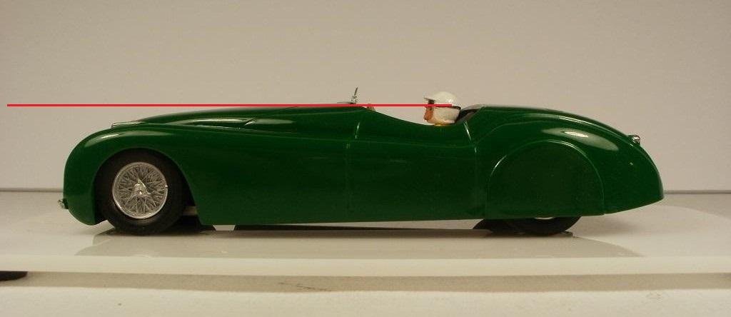
Just look at his line of sight. He doesn’t even have a clear view of his own horizontal, let alone anything below it. He has a good view of the sky.
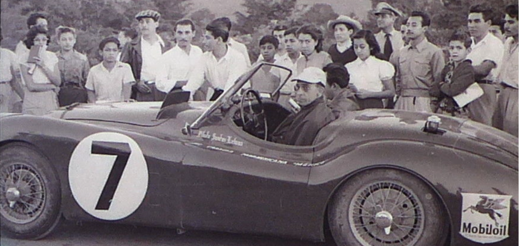
(This is the viewing height you need to see the road ahead in an XK120. Photo from S32 “La Carrera Panamericana V”. )
Now, Ken, this is your car, and you can build it the way you want; no one is going to force you to change it. If you don’t want the pilot able to see the road ahead, that’s up to you. If that then becomes the acceptable standard for this club, then so be it. But let’s not bring in bugs, rocks and losing an eye into the argument, just to pretend that this pilot can see the road ahead. Anyone else looking at this forum with fresh eyes would think ‘what are these guys arguing about, that driver can’t see a damn past his dashboard!’ Facts is facts! You can’t twist the truth / it knows no regulation / just causing too much frustration!
Hi Chris:
I’ve admired your chassis builds for many years, the scratch-built as well as the Scholer and Plafit examples you did for Mark’s site.
This one is another interesting example. It looks like there may be some degree of torsional effect to it even without any hinging. Since your testing shows that it performs well, I am inspired to try a much simpler design than the ones I have been planning. (That’s something Art has been advising me to do for a long time now, but I’ve been stuck in the mindset of the chassis that I am used to, with the multiple layers and complex spring posts.)
Good idea with the extra posts to control body roll. I’ve also encountered the problem and was planning to use L-shaped styrene attached inside the side panels of the body.
I came across another article of yours on Brass Cutting, in homeracingworld from a while back. It also shows some of your fine work; I hope you don’t mind my adding it here for everyone else’s reference:
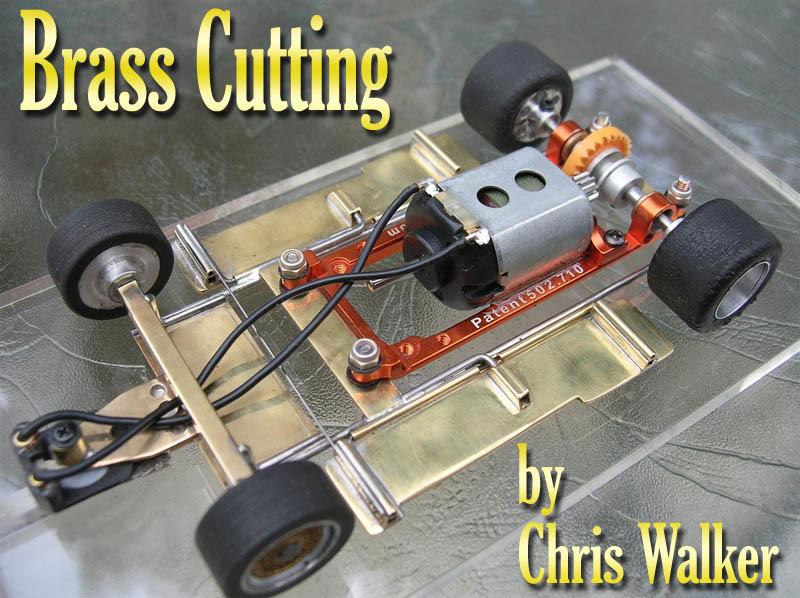
( PS: Interesting motor pod; is there a current supplier available for it ? )
Excellent approach, Ken. Thoughtful methodical technique, very practical as well. Should help us avoid some sticky problems while spray painting. Just an afterthought: The other problem I’ve encountered once in a while (not very often!), is premature loss of pressure. Don’t you hate it when that happens! There’s still stuff inside, but you just can’t make it go out the nozzle!
Thank you for your thoughtful and practical advice, Ken, Bill. Unfortunately, I just can’t leave a defect, (especially when it will give a deeper layer of translucent metallic paint at the indentations). It’s just a standard I set for myself, not trying to outdo anyone; I don’t impose it on others. It’s my character flaw! An idealist by nature, a theorist by training; it’s my strength and my weakness, mainly a weakness lately!
OK, Ken. I was looking at your sideview photo; it shows the pilot’s actual line of site. (You’ll find that even a horizontal line through his goggles hits the top of the steering wheel and dashboard. Use the front of the googles strap line as reference since his head is tilted up slightly. In any case, no way to see road ahead.) But enough on this; good job on the car anyway.
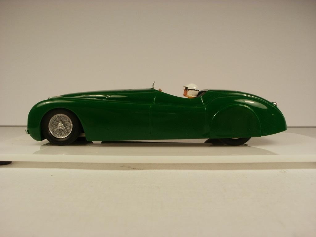
I am feeling very inadequate! I see most members producing all these great builds, and I have nothing to show for. I’m sorry that I don’t have the needed time to devote to the hobby. I feel like I’m letting down the cause, letting down the other fellows. (No need to reply; not looking for sympathy.) I will try to help on the forum whenever I can.
Thanks for your note Ken. Sorry for my late reply, I don’t often get time to check the forum on time. You’re right; I’ve encountered some very useful information hidden in the body of other posts. It’s often hard to find it later. I’m not sure that my suggestions to Luis fall into the category of ones worth duplicating, but I will do a bit of editing and post it in the ‘Resources forum, How to paint it’.
Again, excellent work all around, Bill. I’ve been planning ahead and looking at my copy of the body. I see four very small dimples/ indentations in the surface of either side of each fin. (Probably a consequence of curing contraction at thick parts of the plastic.) Not very visible, but will become more apparent with the light metallic colours I am considering. I used to apply body putty when I built 25’th scale static kits as a kid, but I’m hesitant to try it on track bodies, worried that it may crack. (Lately I have tried my own concoction, a solution of liquid cement and polystyrene, but the adhesion is not perfect along the perimeter.) Did you notice any such effects on your copy? Either way, any suggestions for a solution? Anyone else have any advice?
Thanks.
I don’t see anything wrong with this as a Sports Car, Ken. Nice colour, (who could argue with BRG?); beautifully executed paintwork and detailing; just add three white rondels and you’re done. Only one simple adjustment needed; this poor pilot is going to have a lot of crashes! Give him a booster seat so he can see over the dashboard and bonnet! (A piece of heavy duty double-sided cushion tape should do the job.)
Thank you, Ken, Bill, for your excellent suggestions. I have made note of them as reference for when I get to the build. With the new body width, I am now working on adjusting my chassis plan.
Regarding the question posed, and input sought: The Jaguar XK120 is one of the best defining examples of a true Sports Car; it would not qualify as an example of any Hot Rod, in my humble opinion.
Great detailing F1Nutz; I don’t think I’ll even attempt a bar in mine!
Very nice job, Luis. I can see some beautiful detailing.
In terms of the experience you were referring to, this example is not one of the easier masking jobs to tackle.
I can’t tell from the photos whether you have done so already, but just in case, do spray the white colour first (perhaps over a Tamiya white primer that goes on finer than the grey). The blue colour will always cover it well.
In terms of the masking, these symmetric patterns are very difficult to replicate from left to right. I’m not an expert, but I’ve had some success with this approach; you may want to try it on your next finishing job. Buy a couple of widths of Tamiya masking tape, thin and flexible. Before doing any painting, stick the tape over the areas – on one side of the body, that you want to stay the light colour (white in this case). Take a pencil, pen, or marker and draw as smooth an outline of the perimeter shapes you want to achieve. (Doesn’t need to be perfect at this stage.) Find a piece of Lexan (clear plastic sheet) from a container of some sort. Remove the strips of masking tape that you have scribed from one side of the body. Stick those scribed strips of tape spread out onto the Lexan sheet. On the back of the Lexan sheet, stick new strips of tape to coincide with the ones on the front.
Remember, your original scribing did not have to be perfect; now the next step does have to be perfect! Find a large sharp pair of tailor’s scissors (made in Germany in the 1950’s !) from your mother’s sewing room! Carefully cut a smooth line (through the three layers) along the scribe marks you made while the tape was on the car body. You now have sections of flexible masking tape back-to-back in symmetric mirror images. Save these until later.
You can now start the first stage of painting. Prepare the body with sanding and washes as you see fit. Apply your choice of primer, fine grade white in this case. Do any follow-up smoothing and further preparation; a second coat of primer may be needed. After curing, apply your light colour finish coat (white in this case). Let cure fully then do any follow-up smoothing.
Now, carefully peal the tape pieces from both sides of the Lexan and place them at the corresponding positions on the car body. Make sure they are stretched properly and that the edges are smooth and tightly adhered to the body. You are ready to start the spray of the second colour coat (blue in this case) over the taped pattern and the rest of the body. Do the appropriate spray steps. Let the final coat cure partly but not to a full hard shell. Now, stop and pray! Carefully remove the tape masks after the final paint is dry to the touch, but still has a bit of flex.
Hope this works a bit for you; I’m no expert. You may be able to improve on the method.
Felix.
Hi gents:
My Gunze Sangyo 1/32’nd kits finally arrived yesterday, after 22 days. I was most interested in the “1957 Cadillac Eldorado Brougham”, but I added the “1963 Ford Thunderbird Blue”, in order to make better use of the high ship rate. The Thunderbird was advertised as the blue cast body, but it came in the red version. I had been planning on light pastel blue colours for each for each, but on the red body, I will have to search for another appropriate colour. In order to go from bright red to light blue, I would have to use the heavier grade Grey primer spray, which would likely hide some of the fine detail.
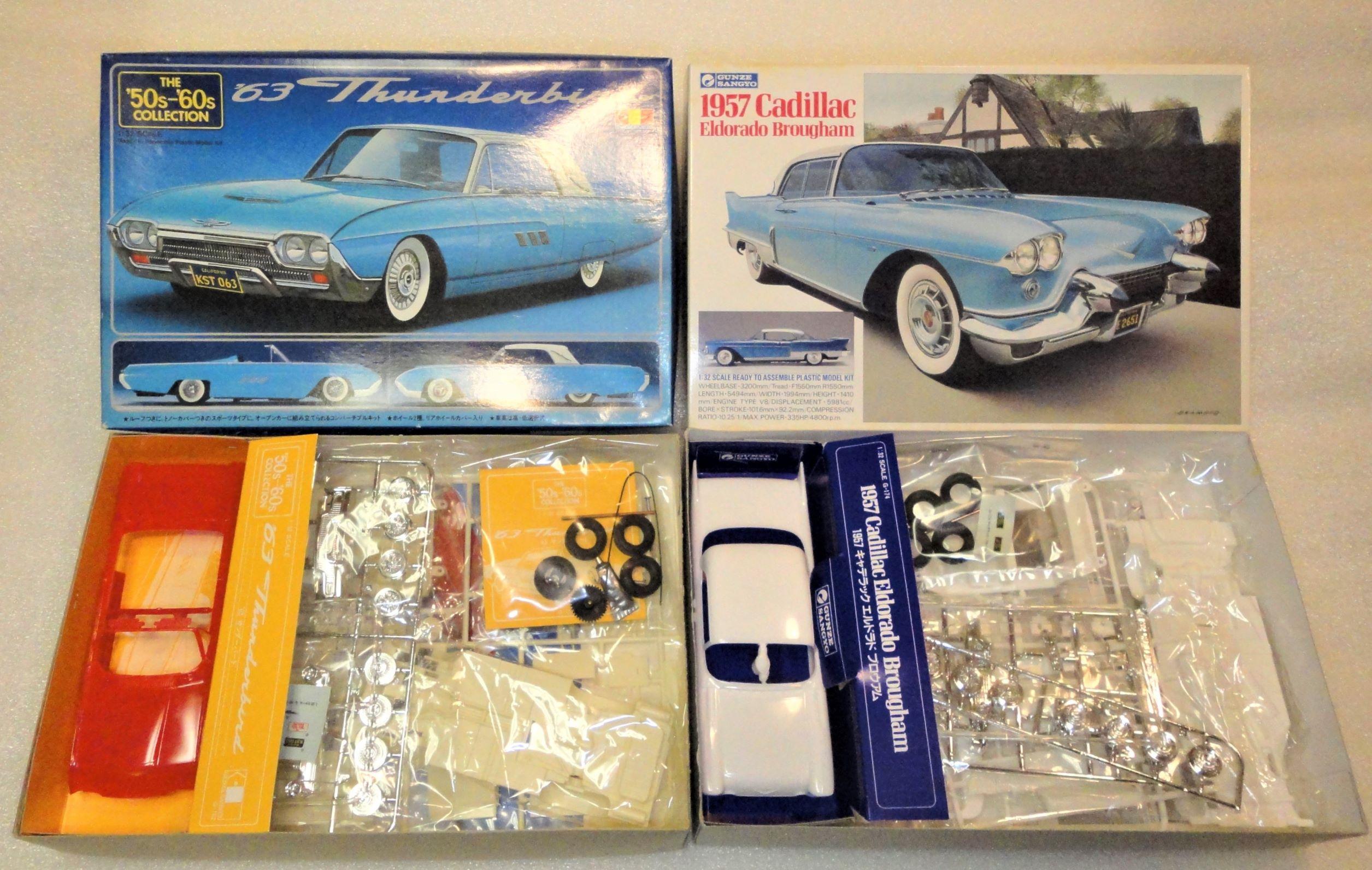
The kits are of fairly good quality, as already noted in this topic. The T-bird body is very light, very thin (and translucent), flexible. The Cadillac body is noticeably thicker. (I did not ‘weigh’ them since one is hardtop and the other isn’t.) They both have wider bodies that the original model I had bought last summer and was planning to use in this Cruiser series, so there is a chance that I may be able to fit a full sidewinder transmission in them. (Gunze has already supplied pinion and spur gears in the T-Bird kit, so maybe all I need to buy is a motor?!)
I am anxious to start on the builds. It looks like some have had a lot of time for the hobby during this lockdown; I’ve been busy as ever, with other projects and a couple of things that came up unexpectedly. In any case, I don’t want to get ahead of myself; the top experts (those without a political agenda) are predicting that we will be in this state for another two years. Even then, I don’t know if we will ever get back to overlapping elbows and sharing the same breathing space. Who knows; we’ll hope for the best.
Felix.
Thanks Ken; you sure have a skill for finding some nice kits!
I could only find one of these from Japan and the other from Hong Kong, both coming to C$90. I did a search under ‘find similar items’ and the one from this seller didn’t appear. I already had the blue ’63 Thunderbird in my watch list from this seller and it showed ‘this item is out of stock’ by the seller. After I found the Cadillac from your note, I looked at the seller’s other items and found that he did in fact have another identical copy of the ’63 Thunderbird (blue). The ’57 Cadillac may have appeared the same way. I found that the shipping cost of $21.50 usd, or C$31 was a bit high for just one kit so I ordered both. I’m now waiting for a reply invoice with the combined shipping. (By the way, Gunze Sangyo made a great line of 24’th scale kits. I was tempted to add their Triumph TR3 listed by the same seller, had it in my cart then dropped it just before I asked for the invoice. It was from their regular series. I already have their Ferrari 250GTO and the Jaguar XKE from their excellent “High Tech” multi media series. Sorry, can’t seem to help myself from referencing that ‘other scale’ – should be banned!)
Thanks for alerting me to the Cadillac listing; I had a feeling that you might come through with an idea! :yahoo:
Hi Ken: Sorry I didn’t see your reply from April 2, 2020 at 11:59 pm, #14384 until now. I’ve been juggling other work, family, and a major offsite project. (In any case, my posts were being blocked by the forum at the time; The author and submit time were listed, but they weren’t publishing and wouldn’t open on the site.) I am impressed by the builds that people have been working on. Unfortunately, I have not been free to spend any time at my workbench.
Yes, allowance for a full interior is one nice advantage to sidewinder/anglewinder transmissions. There are quite a few others. I should write up a full discussion at some point.* The purpose of my March 15 post was to try to get people to consider the sidewinder alternative; just makes a lot more sense for many reasons, whenever there is room available.
Your car looks very good, probably even better than the photos. I built a 25’th scale AMT static model of the ’63 Thunderbird when I was a kid, and with that nice integrated tonneau cover as well. I had planned to use one for my car in this series (different car from yours- leaving it a little mystery for now). If I can’t make the right tonneau shape from scratch I may just do the car in hardtop. I’ve also been trying to locate the Gunze Sangyo kit of the ’57 Cadillac Eldorado Brougham, but the only ones I can find come to C$89 + 5% PayPal exchange surcharge; a bit too high. Keep up the good work.
* There is nothing quite as practical as, the right theory !
Thank you for your notes, Ken and Art.
For the sake of accuracy, when I said at the top that “(I posted this on the weekend; it was listed for a while then disappeared.)”, the weekend I was referring to, was two weekends ago. I had originally submitted it on Sun Mar 29. When it was still blocked the following day, I re-wrote it. This has happened with a number of my posts and event registrations since the end of January, and Art has been trying to correct the problem.
In terms of the topic itself, Art’s conclusion, above, is most appropriate. Of course, anyone is welcome to use my water tire-cleaning kit before any race I am attending. A few people have already tried it. (I’m sure others can build one even better; Ken, where are you!) 😉
Very nice job, Ken. I like a lot of the details. I had noticed your posting a week or so ago, but was waiting for an update.
I also like the idea of the concealed guide keel, being placed behind the front axle. (I have long been thinking of using that placement on a few 30’s vintage cars, 50’s GP’s such as the Talbot Lago, and Hot Rods, in both scales.) You had mentioned that you were testing the idea. Have you had a chance to compare how that placement performs under race conditions?
I’ve often wondered if there is a ‘golden triangle for slot racing’ (like the golden rectangle in Classical Architecture). That is, is there an optimal ratio of the perpendicular distance from the guide post to the rear axle, divided by the rear spur? (For discussion, let’s call this the ‘keel ratio’.) Placing the guide behind the front axle also changes the ratio. Is there a value of this ratio that would give the best overall performance for the car?
I’ve searched far and wide for an answer, even consulting a few of the life-long scale racing gurus in Europe, but have not found an answer. Like the wheelbase factor, perhaps it depends on the type of track (how curvy?) and size of the track. (Some of their tracks are literally larger than our hockey rinks!)
Most 24’th scale chassis have a separate guide holder that is adjustable (see photo below). I know that the competitive racers use different guide post positions along with different gear ratios, depending on the track they are running at. This indicates that there must be an optimal guide position for any given track. The only related evidence I recall personally is that Carrera Evolution-series F1 cars have the guide post behind the front axle and they handled very well. So I wonder if you’ve had an opportunity to test your idea; how is this car handling during a race, compared to your other cars with the guide in front of the front axle?

Adjustable guide holder. (One of my 24’th scale chassis. Initial test setup, still need lots of adjustments.)
You’ve done a great job all around Ken. But something has to be done about all the exposed hardware! Most of the chassis and much of the motor are clearly visible from the sides, as in your photos above. No fault of your own, since you are working in the confines of the rule set for Hot Rods. (In 1/24’th scale club series or international meets, a key rule is that ‘No part of the chassis shall be visible when the finished car sits on the tech block and is viewed at eye level.’ ; a very sensible rule, though we don’t necessarily need to go to that extent here.) I know that you don’t want to cut into the inner body since you’ve already removed the fenders. Of course the chassis exposure can be reduced, though not fully, by shortening the rear uprights/bearing holders, but that would result in an even higher centre of mass for the whole car. The limiting factor seems to be the overall width, the 50.8 mm rear ‘spur’, so that’s probably where the best solution lies. If we allow for an increased width, it may allow you to drop the body, as well as to add some wide rear tires as on many Hot Rods. (It looks like some of the other Hot Rods on the track may have run into the same problem due to the width restriction?) Certainly many Hot Rods retained the narrow tires of the original 1930’s cars but many, like some in your photos above, were built with widened fenders, and even with large dragster slicks.

‘Bucket-T Hot Rod’
Anyway, just a few ideas.
Felix.
I used to be one of the sharpest tools in the shed; now I’m just a slot-head!
Hello Gentlemen Racers and fellow ‘Slot Addictos’:
Art’s summary and Ken’s reply sound very good, and workable. (F1NUTS: the car and driver look great!)
Just for interest, if anyone is curious as to why I prefer to avoid inline transmissions, I have devised a test you can do at home to make your own observations. My hypothesis is that during increase in the motor RPM there will be an observable reaction (other than acceleration) onto the chassis as a whole, that will not be conducive to the car’s performance.
Along with other limitations, there is an inherent inescapable deficiency in the dynamics of the inline system. I can show you all of the torque, angular momentum, and force-couple equations, but we may just get bogged down in equations and loose the physics behind them; it would be much more convincing for you to see the effect for yourself.
Take an inline-drive car and remove the body. Attach a long flexible thin conductor (such as a lead wire) to each of your guide brushes (either by tape, or looped under the brush, or connected to the brush to motor-wire junction). Loop a long thin string to the front of the chassis around the hole for the guide. Connect the other ends of your flexible wires to your power supply set at about 9 V. Hold up the string and flexible wires so that the chassis hangs freely in the vertical plane. Switch on your power supply, and observe what happens as the power surges, (as it would when you quickly press the controller trigger).
I’ve tried this just now with a 32’nd scale car. The result is evident and does have an effect on the dynamics of the chassis. (The effect may be subtle – but still present, if you are using a motor with a light armature, small armature radius, or slow rotation [The first two factors would contribute to a low moment of inertia. The three factors together would now contribute to a low angular momentum.] .) But I should note that, because of the lighter armatures in 32’nd scale, this may have no net effect on the overall performance of the car (in this scale). However, my participation in the hobby has never been about lap times, or about beating out the other guys; I just want to build the best chassis possible with my limited abilities, so it’s more of a theoretical consideration for me.
If you give it a try, let me know what you observe, and we can do the follow-up analysis.
Felix.
I used to be one of the sharpest tools in the shed; now I’m just a slot-head !
There is nothing quite as practical as, the right theory !
Some very interesting ideas here. I’m hoping that for this series, people won’t be stuck in an inline marriage!
I bought an excellent kit last summer and have been planning the chassis, body finishes, and detailing. I was intending to just run it a few laps once in a while, just for a change in scenery. I’m sure most will find it interesting. (I won’t say what it is just yet; it’s not one mentioned so far.) Now that there may be a series, it will fit in perfectly, but can’t be run in a race if the requirement is going to be inline rear motor.
As I say, I’ve already done the basic chassis plan, and it will be sidewinder drivetrain. These cars have lots of room for a sidewind transmission. There’s no point using an inferior drive train assembly, unless there are space restrictions such as in 50’s GP cars. (Hey, if your marriage is going great and you are still deeply on love with inline, that’s fine; you can still use it, but let’s not restrict it to that!)
Just an afterthought: Perhaps the most appropriate drive train for this series would be front motor mounted directly behind the front axle, to rear drive inline! If we are going for realism, that may be the best assembly. (And it would also avoid some of the deficiencies and limitations inherent in rear motor inline.)
This could be a very interesting series; a good range of colourful cars and an opportunity for creative chassis and bodywork.
“Functioning front steering!”; what’s that? I didn’t say anything at all about front steering; not me, I didn’t do it! Hmmm!? You must be using some higher order deductive reasoning. You’re making my build plan even harder than it already is!
I think I got too ambitious and detailed in the plan, for my first build; also, the fine details seem harder to do in 32’nd scale. That’s one reason I set it aside; I should do a more standard build, perhaps on a closed wheel car as a start. I’m still having difficulty adjusting from the other scale, totally different world (as you can see from the photo of my chassis, above).
Thanks for your note, Ken. It’s good to hear that the car is performing very well with that guide post position. Very nice build. Sorry to hear about your Dad; it must have been great to sit in that real car with him.
Yes, I agree; stay within the current rule limits on this one. Perhaps it may be worthwhile at some point, to consider a Hot Rod unlimited sub-class in order to allow for these adjustments, as we have with other classes?
Felix.
I used to be one of the sharpest tools in the shed; now I’m just a slot-head!
Very nice job, Ken. I like a lot of the details. I had noticed your posting a week or so ago, but was waiting for an update.
I also like the idea of the concealed guide keel, being placed behind the front axle. (I have long been thinking of using that placement on a few 30’s vintage cars, 50’s GP’s such as the Talbot Lago, and Hot Rods, in both scales.) You had mentioned that you were testing the idea. Have you had a chance to compare how that placement performs under race conditions?
I’ve often wondered if there is a ‘golden triangle for slot racing’ (like the golden rectangle in Classical Architecture). That is, is there an optimal ratio of the perpendicular distance from the guide post to the rear axle, divided by the rear spur? (For discussion, let’s call this the ‘keel ratio’.) Placing the guide behind the front axle also changes the ratio. Is there a value of this ratio that would give the best overall performance for the car?
I’ve searched far and wide for an answer, even consulting a few of the life-long scale racing gurus in Europe, but have not found an answer. Like the wheelbase factor, perhaps it depends on the type of track (how curvy?) and size of the track. (Some of their tracks are literally larger than our hockey rinks!)
Most 24’th scale chassis have a separate guide holder that is adjustable (see photo below). I know that the competitive racers use different guide post positions along with different gear ratios, depending on the track they are running at. This indicates that there must be an optimal guide position for any given track. The only related evidence I recall personally is that Carrera Evolution-series F1 cars have the guide post behind the front axle and they handled very well. So I wonder if you’ve had an opportunity to test your idea; how is this car handling during a race, compared to your other cars with the guide in front of the front axle?
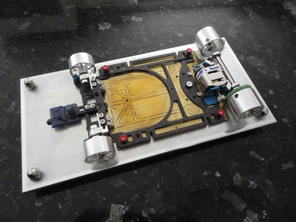
Adjustable guide holder. (One of my 24’th scale chassis. Initial test setup, still need lots of adjustments.)
You’ve done a great job all around Ken. But something has to be done about all the exposed hardware! Most of the chassis and much of the motor are clearly visible from the sides, as in your photos above. No fault of your own, since you are working in the confines of the rule set for Hot Rods. (In 1/24’th scale club series or international meets, a key rule is that ‘No part of the chassis shall be visible when the finished car sits on the tech block and is viewed at eye level.’ ; a very sensible rule, though we don’t necessarily need to go to that extent here.) I know that you don’t want to cut into the inner body since you’ve already removed the fenders. Of course the chassis exposure can be reduced, though not fully, by shortening the rear uprights/bearing holders, but that would result in an even higher centre of mass for the whole car. The limiting factor seems to be the overall width, the 50.8 mm rear ‘spur’, so that’s probably where the best solution lies. If we allow for an increased width, it may allow you to drop the body, as well as to add some wide rear tires as on many Hot Rods. (It looks like some of the other Hot Rods on the track may have run into the same problem due to the width restriction?) Certainly many Hot Rods retained the narrow tires of the original 1930’s cars but many, like some in your photos above, were built with widened fenders, and even with large dragster slicks.
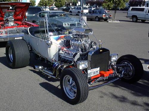
‘Bucket-T Hot Rod’
Anyway, just a few ideas.
Felix.
I used to be one of the sharpest tools in the shed; now I’m just a slot-head!
Ken, just make your own.
I made some similar ones long ago, for a Lola T70. I used K&S aluminum tubing and a steel rod. I spun the steel rod and tapered the end into a smooth concave profile. I then pressed and spun the end of the steel into the cut end of the alu tube. The material is fairly malleable, so I was able to achieve a nice flair on the ends of the alu tubes, without any breakage. From what I see in the photo, it doesn’t look like you need as sharp or as extreme a flair, and you will be working with a larger initial diameter, so it should form easier. You can then add whatever finishing effect you want into the surface of the bare metal.
Good luck with it; it should be a interesting variant on the Lotus 30.
March 4, 2019 at 9:15 pm in reply to: 1934 Aston Martin Ulster kit for the Pre-War GP series in S32 #10812Sorry for my delay; I have not been keeping track of the forum. Previously I had received automatic notifications whenever a new posting occurred. Talking with Art yesterday at the Grp25 show, I was informed that what I had assumed to be ‘automatic pre-programmed notifications’ were in fact ‘automatic manual’ ones!
Unfortunately I have no progress to report on the A.M. Ulster car. At the last stage I had been waiting for another delayed delivery of a specially dimensioned brass profile, one that I needed for the combined motor-haulter/bearing-holder. In the interim I got involved with a house project, and from there onto other projects. Then there’s the 24’th scale work, building, racing, and responsibility for tech inspection on two of the series. So I finally realized that I had to pack up all of the Ulster parts into a bin, and throw in a couple of moth balls!
Just a bit of info that may be of some use. I’ve often wondered about what I would call the ‘golden triangle of slot racing‘. Is there a best proportion for the distance between the rear axle to the guide post, to the base width formed by the rear wheels? (called rear spur? – not rear track, since track is measured center to center on the tires) Is there a ratio of these two measurements that would give optimal speed and handling on straights as well as turns? I haven’t been able to get an expert opinion on this; I imagine it may be different for different cars and different tracks.
The related question is the location of the guide post relative to the front axle, as has come up on these vintage cars. I have a relevant example. A pair of F1 cars came as part of a Carrera starter set I bought long ago. The wheelbase on these is 95 mm, the width between the outer edges of the rear tires is 60 mm, and the guide post is a full 15 mm behind the front axle. I recall that these cars handled very well at high speeds throughout the track, better than the GT cars. The wheelbase on the Alfa model is 98 mm long, and the rear base width is 48.5 mm. So this should be a good test to see how a similar guide position handles on these vintage cars.
Looks good Art. This is the kit that I have, but in the MPC labelled re-box; the rest looks to be the same (my post, June 25). When I got frustrated with planning the Ulster build, I was going to set it aside and go ahead with the Alfa first. I had thought it may have been easier since the body doesn’t wrap around to a pan chassis. (I finally have all the details of the Ulster planned out.) What you’ve done so far on the Alfa looks like a nice start. Lots of variants with the original cars, so we can easily go with different colour combinations even if we have a few of these; I may want to use some of your windscreen parts. I still haven’t found the function of those boxes projecting forward from the rear fenders; most of the photos I had seen showed small brass padlocks attached to them. It will be great to see all of these vintage cars running together on your track. I’m curious to see the rest of the build; Good luck with it.
Felix.
August 4, 2018 at 11:25 pm in reply to: 1934 Aston Martin Ulster kit for the Pre-War GP series in S32 #8147Art, MiA, F1Nutz, thank you for your words of encouragement. Each of your cars looks excellent and seems to run beautifully. I should have done a similar build. I adopted some overly ambitious objectives without having any experience in scratch building. Also, my frame of reference is 24’th scale ‘Euro-mechano’ structured chassis, everything bolt-together, modular, adjustable, replaceable. I’ve done quite a bit of innovative building there, with designing and fabricating upgrade parts out of brass, aluminum, phenolic plate, and carbon fibre plate, to solve various structural and performance problems. But I have not yet done a full scratch built chassis.
With that mindset, I think some of my plans and objectives for 24’th scale work crept into this project. ( I have been developing plans for building 24’th scale racers from the Heller kit of the1930 Bentley Blower, 1932 Alfa Romeo 1750cc Zagato, other 30’s vintage kits, as well as the Heller kit of the 1948 Talbot Lago T26C, and the 1975 Ferrari 312T. ) Unfortunately, I’m new to 32’nd scale and don’t have an experience based understanding of what works well and what doesn’t in this scale. Personally, I’m finding that some of the parts designs, sizes, and imperial measurement units are very awkward to work with. Also, a lot of details are harder to do in 132! So, I continue to stumble along as best I can. In the mean time, the expert advice from Art, and others, is of great help.
I received delivery of some more parts at the end of the week. However, fitting together the axles and bushings/ bearings into the chassis is still a major problem at the front end. It would be easy if I didn’t want to keep the current suspension structure and add detail, or keep the drum brakes in place. The inside hub bosses on the vintage Alu wheels, the bushings/bearings, and the drum brakes, don’t fit properly together. Also, there are other things I want to do on the car that I won’t disclose at the moment, for fear that the men in the white coats will come to carry me away today!
Thanks again. Felix.
August 1, 2018 at 11:33 pm in reply to: 1934 Aston Martin Ulster kit for the Pre-War GP series in S32 #8125The Story So Far – sorry I don’t have more finished work to show.
Thank you for your note MiA.
I thought I would give a progress report, though there is not a great deal of progress yet, and much of it is still not visible. I got the wheels, motor and a few other parts from Art. I am now waiting for delivery of some other key parts, including flanged bearings and bushings. Until I can get the axle setups I can’t finish the measurements and continue planning the details of the chassis. I have the Rear suspension parts figured out. The Front is going to be much more complicated, especially for what I’m trying to do.
With this car, a Normal person would build the chassis to the right length and height, cover the axles with tubes, cut out the bottom of the body shell and attach the upper part to the chassis. Or they may retain some of the suspension detail from the kit and cut a slot for the axles to pass through, as some manufacturers have done. I sometimes wish I was Normal !
I am trying to retain all of the detail from the model kit, add a few extra details, then plan my chassis to fit within. That presents many problems. For example, in the model, the rear suspension has leaf springs under the transmission axle, which then has scissor-like dampers above it. All of this is above the chassis pan. I will be putting the in-line drive axle in place of the model kit axle, and surround it with those other components, all sandwiched between the pan chassis and the main upper body. I will have stationary drum brakes on the inside of the aluminum wheels. I should be able to support the rear bearings or bushings and axle from inside the body shell. I have a few plans for the front axle, suspension and inner wheel hubs, but I don’t know which will fit until I get the rest of the components. Either way, none of the designs will be easy to build; I’ll leave that description for a later post.
I’ve thought more than once or twice, that I may have ‘bit off more than I can chew’. I really like this car and want to do a detailed build on it. But it may be better for me to set the project aside; possibly start with one of my others from this series which does not have a closed pan chassis, or else do a closed wheel car like the Ferrari 312PB that I’m planning. Considering that I have never built a 1/32’nd scale car and never done a full scratch build of any type before, this may be too ambitious a project to start with.
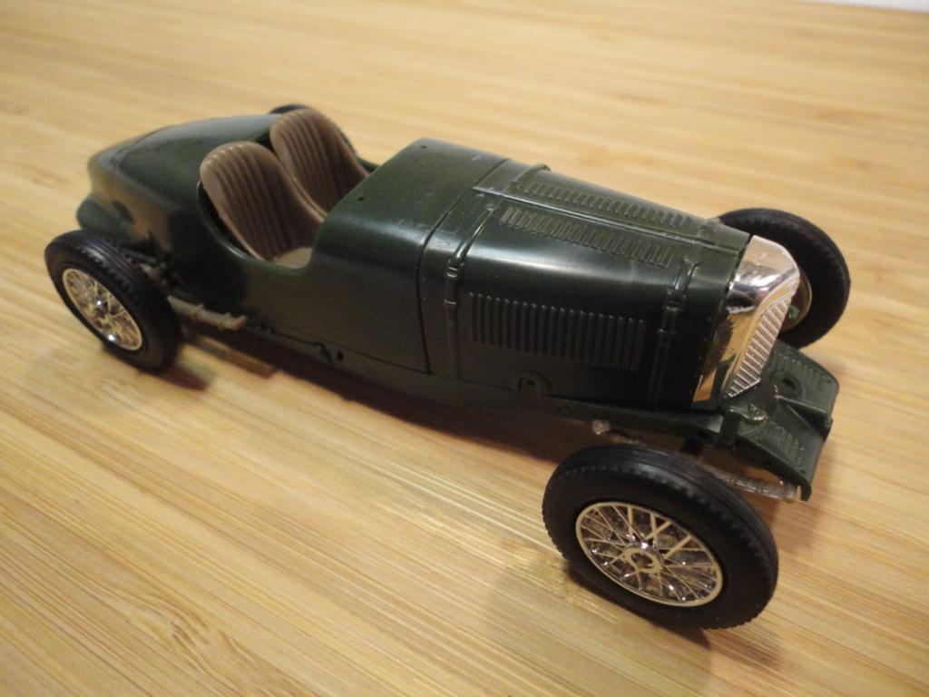
Here is another view of the kit car.
(Only the three pieces of the chassis pan are fused/ liquid welded; everything else is temporarily held together with either double-sided tape, ‘shoe goo’, or masking tape.)
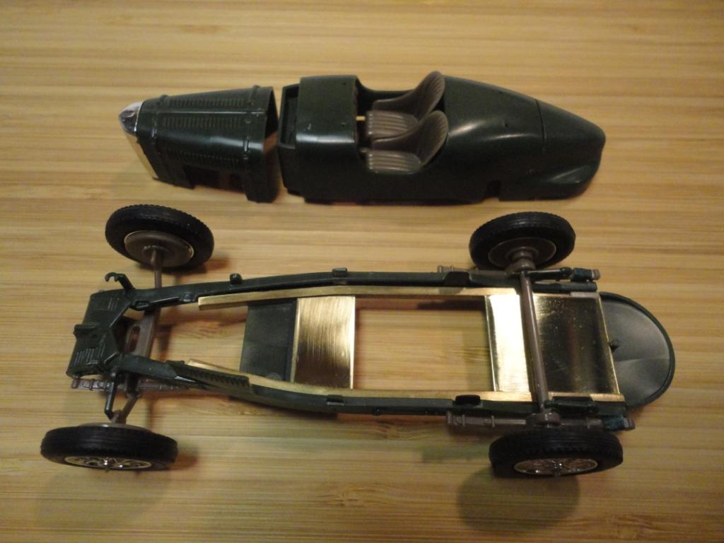
This is the start of the brass chassis (doesn’t look like much, but took a lot of work to get the details).
Side rails are 3/32” square tube, curved along two directions to fit smoothly against the plastic chassis. The brass plates are 1/32” sheet (as I was de-burring the cut edges I discovered that this stock is far from planar so I had to sand it flat – that’s why it’s shiny). The plates are over-sized at the moment in order to allow a wider range of contact positions. They will be cut out to accommodate the motor and drive train, then drilled to lighten.
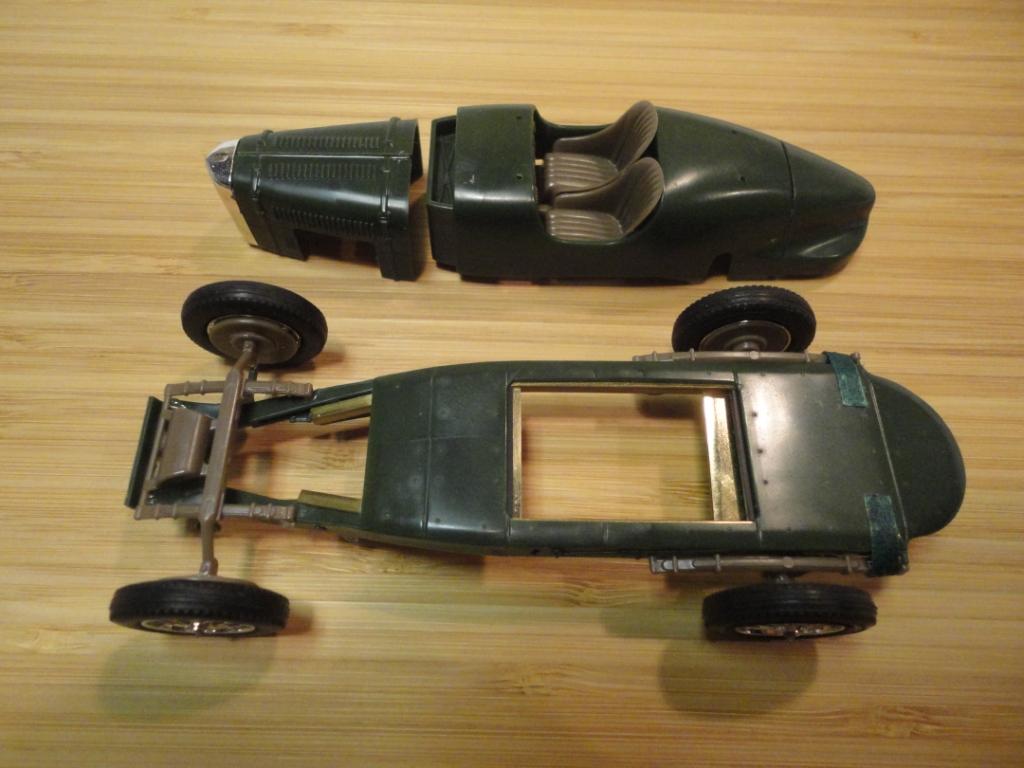
Here is a bottom view, including the front suspension that I will be working with.
I have figured out a few options of how I’m going to work within the front suspension and wheel hubs – it will be the most complex part of the build. I have to wait for delivery of the other parts before I can test what will fit and how. I still have to plan how to work in the guide keel, and how to connect that whole assembly to the rest of the brass chassis (without cutting out much of the model detail).
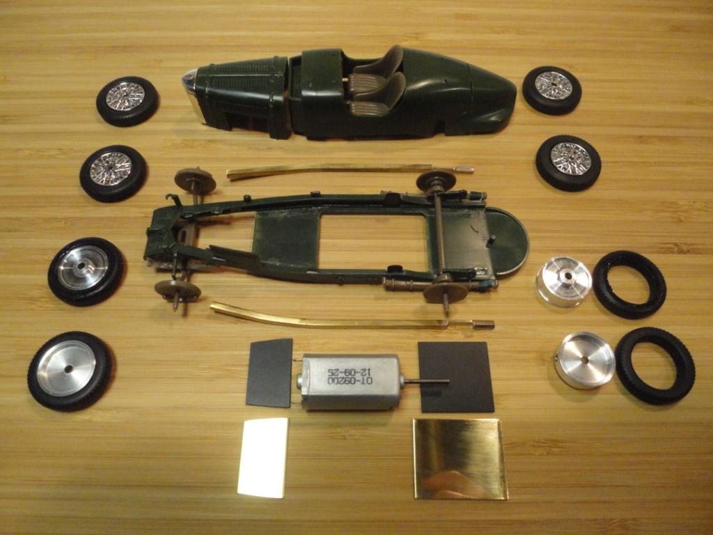
Here are some of the components separated out.
(The black plates are 1 mm polystyrene. They will be fused to the inside surface of the green chassis pan to provide enough strength to hold counter-sunk screws which will thread up into the brass plates. Those joints must be strong enough to hold any stresses and strains between the whole plastic pan and body, and the whole brass chassis.) (Soldering together the brass components precisely will be hard enough as is, even with a jig. Now I need to join the brass plates to the square side rails with a 1 mm gap underneath. I’m hoping I can find 1 mm thick aluminum spacers.)
A great deal of more work to come. I’m sure there will be other new problems encountered. Maybe now’s the time to quit!
Hope to see you at the races. Felix.
June 25, 2018 at 11:24 pm in reply to: 1934 Aston Martin Ulster kit for the Pre-War GP series in S32 #7292Thanks for the info, F1NUTZ and MIA.
I have some casting compound that is very hard but not brittle, and appropriate to use in chassis components. I got it in order to mould suspension uprights and bearing holders for 24’th scale work, but haven’t tried it yet. It may be worth trying it for casting rims, if the appropriate size cannot be found in aluminum.
The Bentley is a great car, can’t wait to see it on the track. Glad to hear that it handles well, so there’s hope for my Alfa. I don’t know about the colour yet; I’ve been looking at photos. The light blue is a possibility, as suggested in the kit instructions, sometimes done with red grill bars and red spokes. The bright red body colour is a possibility, or the deep red more typical of Alfa’s may be best.
June 25, 2018 at 12:19 am in reply to: 1934 Aston Martin Ulster kit for the Pre-War GP series in S32 #7278Thank you for your note, F1.
I finally received my 1933 Alfa Romeo 8C 2300, that I mentioned earlier. It’s an MPC re-box of the original Airfix kit from 1969. It was issued 6 times between 1969 and 2004, twice under MPC in Michigan. The moulding and overall quality of the Matchbox series seems to be better. They are made by Lesney Products, from Essex England, 1975 engraved on the chassis. The MPC body is moulded in L/R halves. There are some strange and unnecessary divisions of other smaller parts. There is no chrome, no rubber tires, and no motor. The windscreen and lenses are roughly moulded. Spokes are surface-moulded onto one face of the rim, although the tires are separate. There are 5 parts to each wheel.
I was surprised to find that this Alfa is described as a “low four seater body typical of its era”. I had only seen artwork of the front end. The kit wheelbase is 14 mm longer than my Ulster, narrower, and higher, at 10 mm from the track to the edge of the chassis. (As with many cars of the era it has large mechanical components well below the chassis frame.) Being higher, narrower, and that much longer, I don’t know how well it will compete as a slot car, though it had a very successful racing career in the 30’s. In any case it should be a good addition to the S32 series.
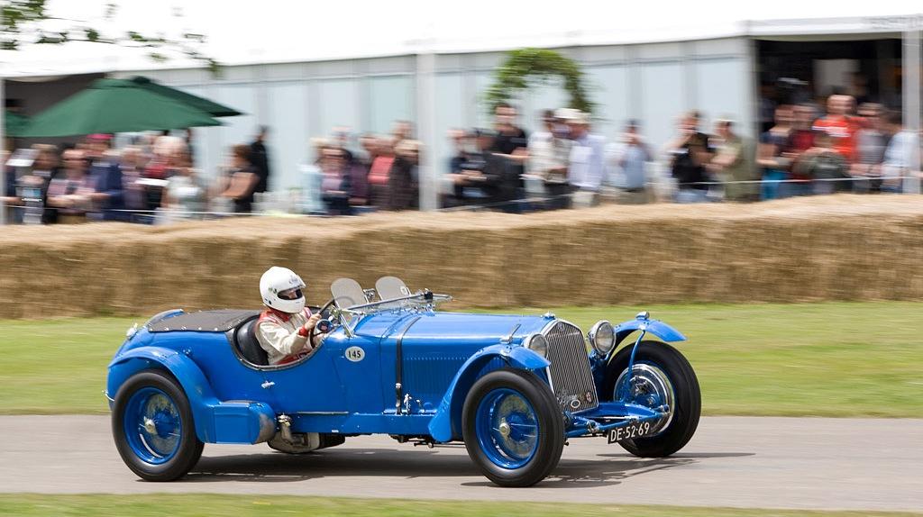
1933 Alfa Romeo 8C 2300, at Goodwood 2008 (Note large tank below the chassis; muffler is under chassis on the left.)
I am looking forward to building the A-M Ulster kit (but I have to continue with some more practical work that is seasonally scheduled on the house). My priority is to build it as true to scale and as detail as possible. I intend to use almost all of the kit parts. Using reference photos, I have continued with some planning and design work, and have most of the details worked out. I’m having difficulty adjusting to the small scale, especially in terms of getting enough room to add the suspension details I want – limited by size, and material strengths. At this point, I can’t proceed further until I get the Alu rims from Art. The geometry of the rims, especially the size and shape of the inside face, may affect the suspension components and the overall track width.
You mentioned after the Ringwood XXVI event, that you had used some cast rims and other components on your Bugatti. I’m curious to find out more about those materials.
Thanks again; hope to see you soon.
Felix.
June 3, 2018 at 2:53 pm in reply to: 1934 Aston Martin Ulster kit for the Pre-War GP series in S32 #7169Hi Art:
Both Rear and Front tracks measured at 53.3 mm, by measuring at the axles themselves without knock offs.
Yes, even looking at a straight top view, the front rolling assembly does look wider, probably because the body tapers to a narrower width.
-
AuthorReplies